Table of Contents
Advertisement
ALIMENTATORE DI FILO A SPIRE SEPARATE
YARN FEEDER WITH SEPARATE COILS
DELIVREUR DE FIL A SPIRES SEPAREES
SCHUSSFADENGEBER MIT GETRENNTEN WINDUNGEN
ALIMENTADOR DE HILO DE ESPIRAL SEPARADOS
İPLİK ARASI MESAFELİ İPLİK BESLEYİCİSİ
MANUALE DI ISTRUZIONE
INSTRUCTION MANUAL
NOTICE D'INSTRUCTION
BEDIENUNGSANLEITUNG
MANUAL DE INSTRUCCION
EL KİTABI
Advertisement
Table of Contents

Summary of Contents for LGL Electronics EcoPower
- Page 1 MANUALE DI ISTRUZIONE INSTRUCTION MANUAL NOTICE D'INSTRUCTION BEDIENUNGSANLEITUNG MANUAL DE INSTRUCCION EL KİTABI ALIMENTATORE DI FILO A SPIRE SEPARATE YARN FEEDER WITH SEPARATE COILS DELIVREUR DE FIL A SPIRES SEPAREES SCHUSSFADENGEBER MIT GETRENNTEN WINDUNGEN ALIMENTADOR DE HILO DE ESPIRAL SEPARADOS İPLİK ARASI MESAFELİ...
- Page 2 Scope of supply: Design, manufacture and after sales service of yarn and weft feeders, measuring winders, stands, creels and oil systems for textile machinery. TRADUZIONI DELLE ISTRUZIONI ORIGINALI. TRANSLATION OF THE ORIGINAL INSTRUCTIONS. TRADUCTIONS DES INSTRUCTIONS D’ORIGINE. ÜBERSETZUNG DER ORIGINALANLEITUNGEN. TRADUCCIÓN DE LAS INSTRUCCIONES ORIGINALES.
-
Page 3: Instruction Manual
Doc no : MAN/ECOPOWER Rev 0 L G L Electronics is gratified by your choice and thanks you for the preference yarn feeder INSTRUCTION MANUAL Service Date: 01/07/14 ISSUED BY: Manager Technical Date: 01/07/14 APPROVED BY: Manager... - Page 4 WARNINGS 1) Power down the yarn feeder’s power supply box mains switch before beginning any power supply hook-up, maintenance or part replacement operations. 2) During standard machine operation, the yarn feeder may suddenly start up without prior warning. CAUTION: the orange lights do not signal that the yarn feeder is ON, but that the feeder has gone into an alarm mode.
- Page 5 WARNINGS ADVICE TO ALWAYS KEEP THE FEEDER IN PERFECT WORKING ORDER AND EXTEND ITS SERVICE LIFE. For an always satisfying performance of the weft feeder over the years, we deem it advisable to provide you with some simple tricks: 1. At the time of installation, passing from the store to the warm knitting environment, Condensation may form on a yarn feeder that has been stored in cold places when this is brought into a warm area.Wait until this is completely dry before connecting it, otherwisethe electronic...
-
Page 6: Table Of Contents
INDEX page GENERAL FEATURES ................8 Main parts - Control and adjustment points ..........8 Overall dimensions ..................9 Intended use – technical and operational features ........10 Handling and storage instructions ............. 11 Input feeler ....................11 Optical output sensor ................. 12 Yarn spool body winding reserve control feeler .......... - Page 7 INDEX page APPLICATION RANGE ................36 TWM tension modulator application ranges ..........36 CONVERSION TABLE ................38 Conversion table for the various yarn count systems ......... 38 TROUBLE SHOOTING................39 10.1 During installation ..................39 10.2 During operation ..................39 STRIPPING AND SCRAPPING ..............
-
Page 8: General Features
1 - GENERAL FEATURES 1.1 MAIN PARTS – CONTROL AND ADJUSTMENT POINTS Main Parts: 1 • MOTOR 6 • OPTICAL OUTPUT SENSOR 2 • TOP PANEL 7 • POWER CABLE CONNECTION 3 • FLYWHEEL 8 • MAIN ELECTRONIC CONTROL BOARD 4 •... -
Page 9: Overall Dimensions
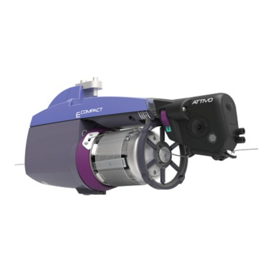
1 - GENERAL FEATURES 1.2 OVERALL DIMENSIONS ECOPOWER featuring the TWM tension modulator Ø100 Weight 2.2 kg ECOPOWER with ATTIVO electronic tensioner Ø100 Weight 2.3 Kg... -
Page 10: Intended Use - Technical And Operational Features
1 - GENERAL FEATURES 1.3 INTENDED USE – TECHNICAL AND OPERATIONAL FEATURES Intended Use: ECOPOWER is a yarn feeder featuring separate coils, suitable for all types of knitting machines or for textile machines requiring yarn feed-in with constant tension. Optimised operation is provided with yarn counts ranging from 500 den (the thicker yarn counts) down to 10 den (fine yarn counts). -
Page 11: Handling And Storage Instructions
1 - GENERAL FEATURES • Permanent magnet synchronous motor. • Motor data: Maximum power: 35 W • Equivalent continuous A-weighted sound pressure level at maximum speed: >70 dB (A) • Operation and storage conditions: - Room temperature: from +10 to +40 °C - Maximum humidity: 80% 1.4 HANDLING AND STORAGE INSTRUCTIONS Never pick the yarn feeder up by its yarn spool body, by its top... -
Page 12: Optical Output Sensor
1 - GENERAL FEATURES 1.6 OPTICAL OUTPUT SENSOR The optical sensor featured by the yarn feeder provides automatic speed adjustment based on the quantity of yarn needed by the machine. For very fine yarn count processing (lower than 40 den), the sensor requires DIP SWITCH settings (paragraph 4 refers). -
Page 13: Yarn Output Detection Feeler
1 - GENERAL FEATURES 1.8 YARN OUTPUT DETECTION FEELER The assembly of this detection feeler onto the feeder output, enables the machine to receive a stop signal that is relayed by the feeder when it detects output yarn snaps/breaks. Installation: once the feeler has been fixed onto the feeder using the nuts and bolts provided on the support bracket, connect up the wire with the three-way connector located on the feeder housing. -
Page 14: Installation And Start-Up
2 - INSTALLATION AND START-UP 2.1 YARN FEEDER INSTALLATION AND START-UP N.B.: Yarn feeders that are moved from warehouse storage into a warmer knitting mill environment may develop condensation; please wait until they are completely dry before connecting them up. Failure to do so may damage the electronic components. - Page 15 2 - INSTALLATION AND START-UP DC version The yellow/green cable (I) must be kept facing the signal lamps (C) (if the ca- ble strip is supplied by LGL, the yellow/green cable (I) can be identified by the arrows (L) printed on the cable strip). N.B.: Ensure that the stand onto which the yarn feeder is fastened is electrically grounded.
- Page 16 2 - INSTALLATION AND START-UP HORIZONTAL SET-UP VERSION For the installation of the feeder onto the machine, proceed as follows: - using screw (G) fix clamp (F) underneath the feeder; fix the clamp onto the machine tube using the grub screws (H) located in the clamp, and position the yarn feeder so that it is set into the exact angle required for operation.
- Page 17 2 - INSTALLATION AND START-UP - Connect up the feeders to the flat power cable (I) by means of the appropriate locking plate (L) then tighten it in with screw (M) located on the housing. CAUTION: when connecting the flat power cable, keep to the printed reference marks showing the exact fixing position (the arrows (N) must point towards the front end of the feeder).
-
Page 18: Power Supply Box
2 - INSTALLATION AND START-UP 2.2 POWER SUPPLY BOX (Available for machines that are not originally equipped with yarn feeders) External view 1. Main ON-OFF switch. 2. Label that specifies the maximum number of feeders supported. 3. Machine STOP function, spool end or broken yarn cable (1). 4. - Page 19 2 - INSTALLATION AND START-UP Internal view 16. Power supply input. 17. Delayed protection fuses 48 V AC. 18. Delayed protection fuses 48 V AC main machine power line. 19. Machine stop cable connection clamps yellow/green wire: common - brown wire: contact normally closed - grey wire: contact normally open...
-
Page 20: Transformer Kit
2 - INSTALLATION AND START-UP 2.3 TRANSFORMER KIT Up to 10 Feeders Flat Cable Machine stop cable Ground to machine (Yellow/Green) 48 VAC from transformer Ground from transformer (Yellow/Green) Ground to machine (Yellow/Green) Flat Cable Machine stop cable Ground from transformer 48 VAC from (Yellow/Green) -
Page 21: Detection Of Yarn Breakage On Feeder Outlet: Kls Kit
2 - INSTALLATION AND START-UP 2.4 DETECTION OF YARN BREAKAGE ON FEEDER OUTLET: KLS KIT This kit allows any irregular use of yarn by the machine to be detected without using any mechanical sensors. These sensors bring about undesired changes in yarn tension that are likely to negatively affect the overall efficiency of the equipment. -
Page 22: Threading And Adjustments
3 - THREADING AND ADJUSTMENTS 3.1 THREADING YARN FEEDER WITH THE TWM TENSION MODULATOR Yarn feeder threading must be carried out when the device is OFF and as illustrated below: PARTIAL THREADING COMPLETE THREADING COMPLETE THREADING ATTIVO VERSION To avoid damaging the TWM we recommend use of threaders that are in good condition with no yarn accumulation around the threader-ends. -
Page 23: Speed Adjustment
3 - THREADING AND ADJUSTMENTS 3.2 SPEED ADJUSTMENT The yarn feeder is provided with a microprocessor and an output sensor that enable automatic speed adjustment that conforms to machine feeder speed. No speed adjustment is therefore required by the operator. For applications that may require special operational conditions, please consult subsequent paragraph 4 herein. -
Page 24: Operational Parameters And Yarn Consumption Kit
4 - OPERATIONAL PARAMETERS AND YARN CONSUMPTION KIT 4.1 DIP-SWITCH SETTINGS Access to the DIP-SWITCH is enabled by snapping off side cap (D) located on the feeder housing. SETTING MEANING (Default Position = OFF) Z Rotation S Rotation SETTING MEANING (Default Position = OFF) Standard optical sensor sensitivity. -
Page 25: Yarn Consumption Kit Installation
4 - OPERATIONAL PARAMETERS AND YARN CONSUMPTION KIT 4.2 INSTALLATION OF THE YARN CONSUMPTION KIT This kit enables display in the relative page on the machine screen, of the simultaneous yarn consumption for all the feeds put together, expressed in centimetres per machine rows. - Page 26 4 - OPERATIONAL PARAMETERS AND YARN CONSUMPTION KIT On the first and on the last feeders that are fitted on the machine, DS4 shall be set to ON (Bus termination). Practical example: A yarn consumption kit has been installed onto the machine and a further number of feeders must now be added on.
-
Page 27: Maintenance Operations
5 - MAINTENANCE OPERATIONS 5.1 REMOVAL OF THE YARN SPOOL BODY Proceed as follows to remove the yarn spool body: 1) Power down the yarn feeders by actuating the main switch located on the knitting machine. 2) Disconnect the flat strip power cable and disassemble the feeder. Lift it off the machine. - Page 28 5 - MAINTENANCE OPERATIONS 4) Unscrew the screw (16) that fastens the plug and remove both items; unscrew the 3 fastening screws (13) that are on the thread winding cone (4) and remove the latter. 5) Remove the absorber that is fastened to the teetered hub by unscrewing the related fastening screws (18).
- Page 29 5 - MAINTENANCE OPERATIONS 7) Remove the winding assembly by taking it out of the shaft; the thin protection sheet (20) can be replaced by unscrewing the 3 fastening screws (21). The assembly shall be later fit back in place by matching the hole where the thin sheet is not fastened, as shown in the figure.
- Page 30 5 - MAINTENANCE OPERATIONS 9) Removal of the front magnet holder (28) must be carried out using the appropriate tool (29) that needs to be fixed onto the magnet holder being removed, using the three fixing screws (13) belonging to the yarn spool body.
-
Page 31: Replacement Of The Main Electronic Control Board
5 - MAINTENANCE OPERATIONS 10) At this point the flywheel (30) can be removed. It is now also easy to replace the ceramic bushing (31) located in the yarn feeder shaft. 5.2 REPLACEMENT OF THE MAIN ELECTRONIC CONTROL BOARD The main electronic control board can only be replaced by a regularly authorised L.G.L. -
Page 32: Component Replacement
6 - COMPONENT REPLACEMENT 6.1 REPLACEMENT OF THE TWM TENSIONER For removal of the TWM tension modulator proceed as follows: 1 Turn the knob until the tensioner (33) reaches the end of its run, at number 0 on the index scale (Figure A). In cases when the ATTIVO tensioner is provided, press the release pushbutton. - Page 33 6 - COMPONENT REPLACEMENT 3) Remove the tensioner (33). Pay careful attention to the way in which the springs are attached to the TWM: the spring-hooks must be hooked into place so that they face outwards from the TWM. This to prevent them from coming into contact with the truncated cone and damaging it.
-
Page 34: Attivo
7 - ATTIVO 7.1 ATTIVO ELECTRONIC TENSIONER ATTIVO is an electronic system that has been purposely conceived to hold yarn tension constant and programmable. The output sensor provides a real- time measurement of the output tension and an electric motor uses this value to adjust the position of the TWM tensioner. -
Page 35: Offset
7 - ATTIVO 7.2 OFFSET Upon first installation of this device, you need to enable the tension sensor to acquire the OFFSET function (mechanical error zero function). Follow the procedure below: - Remove the yarn from the tension feeder. - Switch off the feeder. - Press the release button and hold it pressed until the device light turns on. -
Page 36: Application Range
8 - APPLICATION RANGE 8.1 TWM TENSION MODULATOR APPLICATION RANGES TWM TYPE K code no. A1N3S930-03 00P / A1N3S930-04 00P / A1N3S930-05 00P) TWM TYPE KL code no. A1N3S930-03 KLP / A1N3S930-04 KLP / A1N3S930-05 KLP) TWM TIPO K TWM TIPO KL - For tensioning strength exceeding 10 grams use of TWM KL is recommended. - Page 37 8 - APPLICATION RANGE With the new version of the chrome ring, it’s possible replace the truncated cone of TWM, keeping the disk, the o-ring and chrome ring already on TWM. With the old version it’s necessary replace the entire group.
-
Page 38: Conversion Table
9 - CONVERSION TABLE 9.1 CONVERSION TABLE FOR THE VARIOUS YARN COUNT SYSTEMS Dtex Dtex 18.000 10,63 29,76 48.000 28,35 79,37 18.140 10,71 48.380 28,57 19.350 11,43 50.000 29,53 82,68 20.000 11,81 33,07 50.800 20.320 33,60 54.190 89,6 21.170 12,50 54.430 32,14 22.500 13,29 37,20... -
Page 39: Trouble Shooting
10 - TROUBLE SHOOTING 10.1 DURING INSTALLATION • If the yarn feeder will not work once it has been fitted onto the machine, (i.e. the orange lights won't light up and the motor won't run), check to see that the flat strip power cable has been connected correctly (par. 2.1 refers). -
Page 40: Stripping And Scrapping
11 - STRIPPING AND SCRAPPING 11. STRIPPING AND SCRAPPING If stripping and scrapping of the machine is required, relative rating plates and all related documents must be destroyed or cancelled. If the machine is to be scrapped by third parties, only authorised centres are to be used for any waste recovery or disposal of the ensuing materials.
Need help?
Do you have a question about the EcoPower and is the answer not in the manual?
Questions and answers