
Related Manuals for Stucke Elektronik SYMAP

Summary of Contents for Stucke Elektronik SYMAP
- Page 1 ® SYMAP - Power Protection - Monitoring - Diesel Control - Power Management User’s Manual...
- Page 2 THE CONTENT OF THIS MANUAL IS FURNISHED FOR INFORMATIONAL USE ONLY. THE CONTENT IS SUBJECT TO CHANGE WITHOUT NOTICE, AND SHOULD NOT BE CONSTRUED AS A COMMITMENT BY STUCKE ELEKTRONIK GMBH. STUCKE ELEKTRONIK GMBH ASSUMES NO RESPONSIBILITY OR LIABILITY FOR ANY ERRORS OR INACCURACIES THAT MAY APPEAR IN THIS DOCUMENTATION.
-
Page 3: Table Of Contents
1.7.3 Digital Inputs and Outputs.....................11 1.7.4 Communication Interfaces.....................11 1.7.5 Extended Board (Optional)....................11 ® SYMAP family ......................12 ® Operation of SYMAP ....................20 Front panel ........................20 Menu Tree........................22 Graphic Pages ........................23 Text pages........................24 2.4.1 Main page ........................24 2.4.2 Meter Pages ........................25 2.4.2.1 Meters Overview ......................26... - Page 4 User’s Manual 2.4.4.8 Synchronization Page ....................61 2.4.4.9 Breaker Counter......................64 2.4.4.10 Contact Wear Page ......................65 ® 2.4.5 SYMAP -BCG, -XG Pages ..................66 ® 2.4.5.1 SYMAP -BCG, -XG Main Page..................66 2.4.5.2 MTU Process pages .......................68 2.4.5.3 MTU STATUS ......................68 2.4.5.4 MTU METERS......................69 2.4.5.5...
-
Page 5: Introduction
For flexibility in commissioning and during use, ® both digital and analog outputs can be used to connect the SYMAP control unit to main switchboard controls. Additionally, a variety of serial interfaces with different kinds of protocols ®... - Page 6 ® library of graphics maintained within SYMAP . Programmed blockings remain active when manual control of the breaker is used. Each of the highlighted breakers in the LCD can be controlled with the keys “O”...
-
Page 7: Symap Protection Functions
SYMAP Protection Functions ® SYMAP provides the protection functions shown in the table 1-1 in accordance to ANSI. The protection functions are based on IEC rules. ® Table 1-1 SYMAP protection functions ANSI no. Protection function Time starting Overspeed Underspeed... -
Page 8: Recording Unit
All data recorded by the unit can be transferred and analyzed via a PC tool. And, regardless of ® power supply, the data store is permanent. SYMAP ’s data recording unit stores the following: • Protection function events, such as activation and eventual intervention •... -
Page 9: Data Recorder (Optional)
For easier management and troubleshooting, event data can be transferred and analyzed via a PC tool. The transfer of data is ® made by a link through a plug on the front panel of the SYMAP device. Diagnostics and Monitoring ®... -
Page 10: Communication
® SYMAP can serve as the main bay controller for the power management system or substation ® system. The following list shows the station system items available through SYMAP • Remote supervision • Remote control • Remote parameter setting • Central registration of measured and calculated values •... -
Page 11: Additional Analog Channels
1.7.5 Extended Board (Optional) ® An extended board can be connected to SYMAP , providing additional in and output channels. The extended board is customized to individual client requirements and can be equipped to a maximum of the following in and output channels: •... -
Page 12: Symap ® Family
User’s Manual ® SYMAP family ® There are three different series within the SYMAP family: Y, X and BC-Series. Table 1-2 shows the standard and optional hardware capabilities of these series. The hardware combination of the Y-Series is limited. ®... - Page 13 User’s Manual ® Table 1-3 Software capabilities of SYMAP family ® SYMAP Series - EC ECG XG BC BCG Type - POWER MANAGEMENT MODULES - Synchronizing unit - Load sharing/asymmetrical load ctrl. - Frequency controller - Voltage regulator - Power factor control...
- Page 14 L1 (+) N (-) Power serial communication Pick up supply CAN1 CAN2 RS485/422 Input 28 29 22 23 24 25 26 27 X 2.2 Drawing BC-F1 ® Figure 1-1 Configuration of SYMAP series (Main Board) ® SYMAP SYMAP_UsersManual_E.doc - 14/89...
- Page 15 User’s Manual ® Figure 1-2 Configuration of SYMAP - EXTERNAL AUX. BOARD/CMA211 ® SYMAP SYMAP_UsersManual_E.doc - 15/89...
- Page 16 Function 42 (Input) Function 60 (Output) Function 43 (Input) Function 44 (Input) Function Function 45 (Input) 24V/DC ϑ PT 100-6 Function 46 (Input) Function 47 (Input) ® Figure 1-3 Configuration of SYMAP - EXTERNAL AUX. BOARD/CMA216/217 ® SYMAP SYMAP_UsersManual_E.doc - 16/89...
- Page 17 The extended board CMA216 will be connected via the field CANBUS to the basic unit. To ® release the communication to the extended board the SYMAP the communication parameters [0308] to [0313] have to be set (1.). For communication of the extension board the communication speed must to be set to 125 KBd.
- Page 18 User’s Manual ® Figure 1-5 Graunding-Instructions for SYMAP ® SYMAP SYMAP_UsersManual_E.doc - 18/89...
- Page 19 User’s Manual ® Figure 1-6 Graunding-Instructions for SYMAP ® SYMAP SYMAP_UsersManual_E.doc - 19/89...
-
Page 20: Operation Of Symap
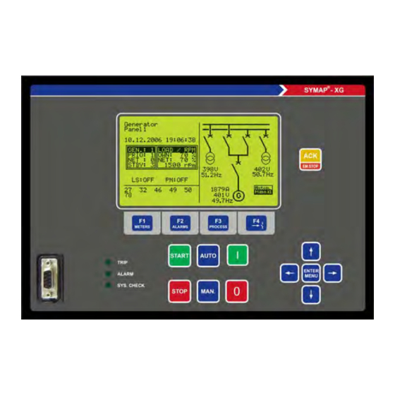
(LCD), the 7-segment displays and single LED indicators a comfortable display panel. The 7-Segment displays, single LED indicators ® and Transponder (lines 1–5, 11) are only available for SYMAP BC/BCG. Figure 2-1 shows in detail the elements on the front panel. - Page 21 ⊗ 13: The push button for acknowledgement of alarms; in help with the stop key an emergency stop can be introduced. ⊗ 14: Navigation block; the navigation block comprises “ENTER” for activating the menu and the arrow keys to move the cursor or display frames. ® SYMAP SYMAP_UsersManual_E.doc - 21/89...
-
Page 22: Menu Tree
LCD. In addition the settings and ® controls of the device can be displayed and modified. In help with the key pads on SYMAP front panel the user will be guided through the menu in a very comfortable way. By pressing “ENTER”... -
Page 23: Graphic
⊗ 11: The gas pressure of the switching device circuit breaker ⊗ 12: The capacitive connection for voltage measuring ⊗ 13: The resistive divider for voltage measuring ⊗ 14: The connection to the consumer ® ⊗ 15: The indication of the operating mode of SYMAP ® SYMAP SYMAP_UsersManual_E.doc - 23/89... -
Page 24: Text Pages
• Alarm/event pages which register all actual and passed alarms and events. • Process pages, showing process information such as synchronizing unit or motor starting states. ® • Control pages, which allow the user to change control modes of SYMAP 2.4.1 Main page ®... -
Page 25: Meter Pages
• If a meter page is displayed it is possible to change the meter pages directly by using F1 (METERS) or the left/right keys. • If a meter page is not displayed it is possible to recall the last displayed meter page directly by using F1 (METERS). ® SYMAP SYMAP_UsersManual_E.doc - 25/89... -
Page 26: Meters Overview
The third section contains the process values active power P, reactive power Q, the frequency F and the power-factor PF. The sign of the power values P, Q is shown behind the symbol. ⊗ 4: The last section contains the actual value of the kWh- and kvar-counter. ® SYMAP SYMAP_UsersManual_E.doc - 26/89... -
Page 27: Current Meters
The unit of the displayed value is A. In the first column the actual measured value is shown. ® Note: With SYMAP -BC series current transformer for measurement and for protection are separate. The equipment registers therefore two different values. The dynamically higher value is indicated. - Page 28 The second column shows the converted percentage values of the first column. In the third column the peak values of the percentage values are stored. ⊗ 3: Use the F2 (MAX RESET) to reset the maximum values. ® SYMAP SYMAP_UsersManual_E.doc - 28/89...
-
Page 29: Voltage Meters
The left side shows the phase voltage of U1-U3, the right side the line voltage. The unit of the voltage values for all 3 sections are V or kV if the nominal voltage parameter [0201] is greater than 99999 V. NEXT PGE ® SYMAP SYMAP_UsersManual_E.doc - 29/89... -
Page 30: Power Meters
Power factor of the feeder BUS; the power factor shows the relation between active and reactive power. ⊗ 5: The second section of the power meters page shows in detail the active, reactive and the power factor of each phase. The active powers are shown with sign. ® SYMAP SYMAP_UsersManual_E.doc - 30/89... -
Page 31: Counter
The max. value of the power counters is 4294967295. The max. value of the working hours counter is 999999:59:59. If a counter reaches the max. value the counting will be continued at 0. ® SYMAP SYMAP_UsersManual_E.doc - 31/89... -
Page 32: Ground Values
The sign in front of the value with + shows inductive power and with - shows capacitive power. ⊗ 5: The angle between GROUND CURRENT 1 and GROUND VOLTAGE 1 ® SYMAP SYMAP_UsersManual_E.doc - 32/89... -
Page 33: Harmonic Waves
The average values of all phase voltages ⊗ 6: Harmonic contents of current phase 1 ⊗ 7: Harmonic contents of current phase 2 ⊗ 8: Harmonic contents of current phase 3 ⊗ 9: The average values of all phase currents ® SYMAP SYMAP_UsersManual_E.doc - 33/89... -
Page 34: Frequency Meters
- max : 60.89 Hz selected graphic - min : 59.72 Hz BUS2 : 60.23 Hz - delta: 0.12 mHz - max : 60.889 Hz - min : 59.72 Hz RESET Figure 2-14 Frequency meters ® SYMAP SYMAP_UsersManual_E.doc - 34/89... -
Page 35: Analog Inputs
At minimum, four analogous inputs are available. If the inputs are activated the actual value is displayed with its defined unit. If an external board is in use further analogous inputs and PT100 inputs are be displayed. ® SYMAP SYMAP_UsersManual_E.doc - 35/89... -
Page 36: Display Setting
BACK EXIT Figure 2-16 Display setting ® The lines 1-4 are only valid for the 7-segment displays (only SYMAP BC/BCG). ⊗ 1: Selection of the unit for current display; % will show the measure feeder current in percent (related to the nominal-rated current; parameter [0200]) and A will show the current in amperes. -
Page 37: Alarm/Event
Alarm/Event Pages ® The second group of text pages contains the alarm and event pages. Within these pages SYMAP provides detailed information about events, alarms and interlocks. By using the detailed event or protection histories, the user can easily follow the recorded events of a process. The “ALARM/EVENT LIST”... -
Page 38: Active Alarms
(event number) and the title of the alarm will be displayed. The alarms within this page are sorted by the appearance time. If more than ® eight alarms are stored by SYMAP the user can scroll the alarm list up and down by using the navigation block. -
Page 39: Alarm Groups
⊗ 1: This line shows the present active number of groups. ⊗ 2: This line shows the present active number of alarms. ⊗ 3: This field shows a list of event numbers of the active groups. ® SYMAP SYMAP_UsersManual_E.doc - 39/89... -
Page 40: Active Events
User’s Manual 2.4.3.3 Active Events This page shows all active events by their number (see figure 2-20). The event list in the appendix ® shows all events which SYMAP can handle. ⊗ 1 active events: ⊗ 2 active alarms: ------ EVENTS ------... -
Page 41: Event History
The last symbol in the line (i, A) shows whether the event has been changed to active status (A) or inactive status (i). ⊗ 2 The number (0000.) shows the scroll index. ⊗ 3 The number (∑: 0010) shows the amount of events actually stored. ® SYMAP SYMAP_UsersManual_E.doc - 41/89... -
Page 42: Detailed Protection History
2.4.3.5 Detailed Protection History ® The detailed protection history stores all events of the protection functions of SYMAP . The events within the detailed protection history are sorted by their time stamp (see figure 2-22). By using the “UP” and “DOWN” keys a certain event can be selected, and with “ENTER” another window containing detailed fault information can be opened. - Page 43 Pickup value of the event at the moment the event status changed and the fault phase (L1, L2 and L3) ⊗ 5: Trip time of the protection event ⊗ 6: Pickup status of all phase currents and voltages at the moment the event status changed ® SYMAP SYMAP_UsersManual_E.doc - 43/89...
-
Page 44: Interlock Page
The diagram number of the interlock logic, which belongs to the corresponding breaker. ⊗ 5: The event number that should be activated to release the control. ⊗ 6: The event number that should be deactivated to release the control. ® SYMAP SYMAP_UsersManual_E.doc - 44/89... -
Page 45: Process
• If a process page is displayed it is possible to change the process pages directly by using F3 (PROCESS) or the left/right keys. • If a process page is not displayed it is possible to recall the last displayed process page directly by using F3 (PROCESS). ® SYMAP SYMAP_UsersManual_E.doc - 45/89... -
Page 46: Motor Page
Calculated trip time (see Service Manual ANSI 49) Triptime: 120,3 s The bar graph shows the 23 % passed trip delay time. The full scale of the bar graph is 100% (= trip). Figure 2-27 ANSI 49 ® SYMAP SYMAP_UsersManual_E.doc - 46/89... - Page 47 Motors Relay (ANSI 66) are allowed. τ τ ⊗ 11: The actual values of cold (tc) and hot (th) are shown, calculated by the settings of parameters [1342], [1343] and [1344]/Thermal Overload Relay (ANSI 49). ® SYMAP SYMAP_UsersManual_E.doc - 47/89...
- Page 48 The second possibility is shown in Curve B. The running phase is reached, when the maximum start time (parameter [1542]) is passed. Curve A Curve B start start [1542] Feedback: Breaker Phase: Starting Phase: Running min. start- max. start- time time Figure 2-29 Motor Start Phase ® SYMAP SYMAP_UsersManual_E.doc - 48/89...
-
Page 49: Engine Overview Page
Working hour counter; this value shows the working hours of the aggregate. The format is hours:minutes:seconds. For the hours eight digits are reserved. ⊗ 6 Active power counter; the kWh register counts the measured active power of the diesel aggregate. ® SYMAP SYMAP_UsersManual_E.doc - 49/89... -
Page 50: Power Management Page
PM status window; this status window gives detailed information about the action of the power management controller. All information, such as load depending starting or stopping condition or send of start and stop order, will be shown. Table 2-2 shows all information the device can display. ® SYMAP SYMAP_UsersManual_E.doc - 50/89... - Page 51 Load depending start condition reached: Start G 1 in: 67 sec The first line shows that Generator 2 exceeds the current limit for start parameter [0909], followed by its actual current and the limit value. ® SYMAP SYMAP_UsersManual_E.doc - 51/89...
- Page 52 All devices within the same net will display the same history regardless of whether the ® SYMAP -BCG, -XG unit is master or slave of the power management. The history stores the start/stop source, the corresponding limit, and the time stamp. A maximum of 100 events can be stored within this history.
- Page 53 Generator 1 was stopped by prio.2 alarm (channel 57). Monitor (CANBUS) STOP G 2 29.11 15:14:55 Generator 1 stopped via CANBUS Monitor at the following time. serial communication STOP G 2 29.11 15:14:55 Generator stopped serial communication (RS422/RS485) at the following time. ® SYMAP SYMAP_UsersManual_E.doc - 53/89...
-
Page 54: Load Page
User’s Manual 2.4.4.4 Load page ® The load control pages provide a load overview of all SYMAP -BCG, -XG devices, which are linked via CANBUS1 (see figure 2-32). The line of the load table is sorted by the CANBUS identifier. - Page 55 Status of power management (PM); if the power management function of the corresponding device is released “ON” will be displayed. If the load sharing function is blocked the user can easy find out, which device is responsible for blocking, since this device shows off status. ® SYMAP SYMAP_UsersManual_E.doc - 55/89...
-
Page 56: Command Window Of Load Control Page
With the down key event [0962] will be activated. ⊗ 8 Mode: In this line the mode of the corresponding aggregate can be selected. The possible modes are: automatic and manual. ® SYMAP SYMAP_UsersManual_E.doc - 56/89... - Page 57 (up and down) has to be used. ⊗ 10 Asymm.load: The asymmetrical load limit for the corresponding device can be set. ⊗ 11 Asymm.PF: The asymmetrical power factor limit for the corresponding device can be set. ® SYMAP SYMAP_UsersManual_E.doc - 57/89...
-
Page 58: Regulator Page
2.4.4.6 Regulator Page ® SYMAP -BCG, -XG provides four controllers to regulate the load, the frequency, the power factor and the voltage of the net. Status, actual measured values and activities of the regulators are shown in this page (see figure 2-41). - Page 59 Difference: It shows the difference between the set point and the actual value. ⊗ 6: Pulse time: The pulse time is the remaining time of the activated control event. ⊗ 7: Break time: The break time is the interval time of the regulator. ® SYMAP SYMAP_UsersManual_E.doc - 59/89...
-
Page 60: Priority Page
2.4.4.7 Priority page ® SYMAP XG/BCG provides a possibility to modify the priorities of all devices connected over the CANBUS. This can be easily done in help with the priority overview page. The page can be found in the menu as follows: Enter > Setting > Priority. -
Page 61: Synchronization Page
⊗ 11 -MIN : 9000 V ⊗ 12 -MAX : 11000 V ⊗ 13 -GEN.: ⊗ 14 -BUS1: ⊗ 15 -DIFF: 0/ 2500V ⊗ 16 CANCEL ⊗ 17 Figure 2-37 Exaple of synchronization unit 1 ® SYMAP SYMAP_UsersManual_E.doc - 61/89... - Page 62 Actual frequency of BUS1 ⊗ 10: The actual differential frequency between BUS1 and the feeder is indicated and shows the maximum of parameter [1002] (Synchronization Unit 1). ⊗ 11: Status of the voltage check, whereby ® SYMAP SYMAP_UsersManual_E.doc - 62/89...
- Page 63 ⊗ 15: Actual voltage of BUS1 ⊗ 16: The actual differential voltage between BUS1 and the feeder is indicated and shows the maximum of parameter [1005] (Synchronization Unit 1). ⊗ 17: With the F2-key you can cancel the synchronization process. ® SYMAP SYMAP_UsersManual_E.doc - 63/89...
-
Page 64: Breaker Counter
2.4.4.9 Breaker Counter ® The breaker counter page shows all breakers, which are managed by SYMAP . Through the graphic selection (parameter [0107]) and the corresponding feedback parameters, the number and kind of breaker are defined. Within the breaker counter page, these breakers and their corresponding switching cycles and life times are displayed. -
Page 65: Contact Wear Page
(parameters [1943] to [1946] in %), and the four switch cycles limits (parameter [1947]-[1950]). Note: The value of a limit in the table is blinking if the corresponding limit is reached. ® SYMAP SYMAP_UsersManual_E.doc - 65/89... -
Page 66: Symap ® -Bcg, -Xg
-BCG, -XG differs slightly from the main page of other SYMAP ® types (see Chapter 2.4.1). In addition to the information provided by SYMAP , this main page shows data about the diesel generator and the status of the loaded net (see figure 2-36). - Page 67 PM: RANGE Load ranges switched on. ⊗ 5: Activated protection functions; this field contains all protection functions (ANSI device numbers) that have been activated (compare with relay settings). (Enter > Setting > Change > Relay > ANSI Device List). ® SYMAP SYMAP_UsersManual_E.doc - 67/89...
-
Page 68: Mtu Process Pages
AL T-AUX 1 Limit 1 HI T-Fuel AL T-AUX 2 Limit 1 Combined Alarm P-Fuel (Rail) --- SS Coolant Level Charge Air Combined Alarm P-Fuel (Rail) --- AL ECU Defect Combined Alarm P-Fuel (Rail) --- Figure 2-43 MTU Status ® SYMAP SYMAP_UsersManual_E.doc - 68/89... -
Page 69: Mtu Meters
--- °C P-Aux 2 Limit 1 --- mbar T-Lube Oil Limit HIHI --- °C P-Aux 2 Limit 2 --- mbar T-Fuel --- °C UL T-Fuel --- °C UL T-ECU --- °C Figure 2-44 MTU Meters ® SYMAP SYMAP_UsersManual_E.doc - 69/89... -
Page 70: Control
: --- ⊗ 8 EXIT Figure 2-45 System control ® ® ⊗ 1: mode: Selection of the SYMAP operation mode; SYMAP provides, depending on the system configuration, three different selection combinations: • LOCAL/REMOTE • LOCAL/REMOTE/SCADA • LOCAL/REMOTE/TEST_ L/TEST_R ®... -
Page 71: Applications
Up- or Down-keys and then pressing “ENTER”. APPLICATIONS Test 1 ON Test 1 OFF Net parallel ON Net parallel OFF Reserved display of Reserved selected graphic reserved reserved EXIT Figure 2-46 Applications ® SYMAP SYMAP_UsersManual_E.doc - 71/89... -
Page 72: Recorder
12,09 6,04 4,03 3,02 2,41 10,81 5,40 3,60 2,70 2,16 9,07 4,53 3,02 2,26 1,81 8,64 4,32 2,88 2,16 1,73 7,25 3,62 2,41 1,81 1,45 7,21 3,60 2,40 1,80 1,44 6,04 3,02 2,01 1,51 1,20 ® SYMAP SYMAP_UsersManual_E.doc - 72/89... - Page 73 • PC: The recorder can be triggered only by the PC - Recorder Tool. ⊗ 9: Setting of the trigger date ⊗ 10: Setting of the trigger time ⊗ 11: Setting of the two trigger events ® SYMAP SYMAP_UsersManual_E.doc - 73/89...
-
Page 74: Mtu
User’s Manual 2.4.5.9 ® SYMAP -BCG, -XG provides a certificated protocol to the MTU controller of MTU. For this application the CANBUS2 port will be used. If the application parameter of CANBUS2 port (parameter [0319]) is set to “MTU303 V1/all” the MTU control page will be displayed within the control menus. -
Page 75: Breaker Control
For the breaker control several settings have to be programmed. ® 1. Graphic selection: SYMAP offers a variety of prepared graphics, which can be shown at the left side of the LCD. In the appendix A3 all possible graphic configurations are shown. -
Page 76: Breaker Control Process
[0112]). After passing the password window the user has two minutes control-release without entering a password again and the selector frame will be displayed around the first breaker. By pressing F4 again or “left” and “right”, the selector frame can be moved clockwise ® SYMAP SYMAP_UsersManual_E.doc - 76/89... -
Page 77: Test Mode
Here the required events for the breaker controls can be set. The process and the operation for the test mode is similar to the mode if the breaker is in service, but the interlock won’t be checked. Table 2-11 shows an extract of the most used events within test mode. ® SYMAP SYMAP_UsersManual_E.doc - 77/89... -
Page 78: Fail Management
• If a breaker has two feedback signals for one switch (e.g. on and off feedback) there are ® four possible feedback situations SYMAP can read, but only two are valid. The fault Event [2913] (undefined breaker position) will be set if •... -
Page 79: Technical Characteristics
User’s Manual Technical characteristics General technical characteristics ® Table 3-1 shows the general technical characteristics of SYMAP -family. ® Table 3-1 General technical characteristics of SYMAP -BC series Description Condition/Characteristics Dimension (w x h x d) 200 x 192 x 81; 279 x 192 x 110; 279 x 192 x 150; Y: 200 x 200 x 87 Weight 3 kg;... -
Page 80: Mounting Instructions
User’s Manual ® Table 3-2 shows the general technical characteristics of SYMAP -X series. ® Table 3-2 General technical characteristics of SYMAP -X and -Y- series No. Description Condition/Characteristics Dimension (w x h x d) 279 mm × 192 mm × 110 mm Weight 3.2 kg... -
Page 81: Binary Inputs And Outputs
User’s Manual Binary inputs and outputs ® Table 3-3 shows the binary inputs and outputs of the SYMAP -family. ® SYMAP also has an external auxiliary I/O board for user to take then enough terminal numbers of I/O. ® ®... -
Page 82: Analogous Inputs
User’s Manual Analogous inputs ® ® Table 3-4 shows the analogous input characteristics of SYMAP -BC and SYMAP -X series. ® ® Table 3-4 Analogous input characteristics of SYMAP -BC and SYMAP -X and -Y- series No. Description Characteristics Current inputs... - Page 83 5.0 %-2000.0 % of 0.1 % 0.5 % 5.0 %-200.0 % 0.1 % 1.0 % 0.1 s-999.9 s +/-10 % of tset All other setting incl. of nominal rated min. 500 ms - preferential trip value ® SYMAP SYMAP_UsersManual_E.doc - 83/89...
-
Page 84: Analogous Outputs
User’s Manual Analogous outputs ® ® Table 3-6 shows the analogous output characteristics of SYMAP -BC and SYMAP -X series. ® ® Table 3-6 Analogous output characteristics of SYMAP -BC and SYMAP -X series Description Characteristics Analog outputs on board Range: 0-20 mA or 4-20 mA/in steps of 90 µA... -
Page 85: Order Information X- And Bc-Series
User’s Manual Order information X- and BC-Series ® SYMAP _ / _ / __ / __ / __ / __ / _ / _ / __ / _ / _ / _ Ordering Code: Project:___________________________________________ Commission:_______________________________________ Available for a. Power supply 12-36 V DC ●... -
Page 86: Extension Boards
“SHUNT1”-output normally closed (standard: n. o.) ● ● k. Nominalfrequency 50 Hz ● ● 60 Hz ● ● Frontpanel type ® ● SYMAP -BC Stucke ® SYMAP -BCG Stucke ● ® SYMAP -BCG Stucke without prog.-connector ● ® SYMAP -BC blue ●... -
Page 87: Power Supply For Extension Boards
Safety device for short circuit protection with selectable set point and time delay ® • Connection to SYMAP basic unit, terminals -X2.1: 18,19 ( lockout relay ) • Borden per phase 1A: at 1 × In (1 A): approx.0,5 VA at 5 ×... -
Page 88: Order Information Y-Series
User’s Manual Order information Y-Series ® SYMAP _ / _ / __ / __ / __ / __ / _ / _ / __ / _ Ordering code: Project:___________________________________________ Commission:_______________________________________ Available for Power supply ● ● ● ● ● ●... - Page 89 User’s Manual ® SYMAP SYMAP_UsersManual_E.doc - 89/89...
Need help?
Do you have a question about the SYMAP and is the answer not in the manual?
Questions and answers