Table of Contents
Advertisement
Quick Links
The information contained in this manual is proprietary. Permission to reproduce all or
part must first be obtained in writing from this company.
Ectron Corporation reserves the right to make specification changes at any time.
LIFE-SUPPORT POLICY: Ectron products are not authorized for use in life-support
devices or systems without the express, written approval of the President of
Ectron Corporation.
Copyright 1996
Ectron Corporation
All rights reserved
Revised September, 2015
For units with serial numbers
62230 and above.
INSTRUCTION MANUAL
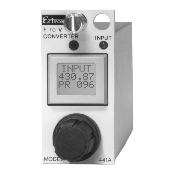
MODEL 441A
FREQUENCY-TO-VOLTAGE
CONVERTER
Ectron Corporation
8159 Engineer Road
San Diego, CA 92111-1907
U.S.A.
858-278-0600
800-732-8159
Fax: 858-278-0372
www.ectron.com
sales@ectron.com
Advertisement
Table of Contents

Summary of Contents for Ectron 441A
- Page 1 The information contained in this manual is proprietary. Permission to reproduce all or part must first be obtained in writing from this company. Ectron Corporation reserves the right to make specification changes at any time. LIFE-SUPPORT POLICY: Ectron products are not authorized for use in life-support devices or systems without the express, written approval of the President of Ectron Corporation.
- Page 2 Ectron's normal rates. Ectron assumes no liability for secondary charges of consequential damages as a result of an alleged breach of this warranty; and in any event, Ectron's liability for breach of warranty under any contract or otherwise shall not exceed the purchase price of the specific instrument shipped and against which a claim is made.
-
Page 3: Table Of Contents
Retention of Settings Input Power Environment Dimensions Compatibility Section III, Operation General Connections Operational-state Diagram Limits vs Settings View Angle Controlling the Model 441A Operate Screen Frequency-set Screen Voltage-set Screen Input-signal Screens Pulses/Revolution Screen Input-sensitivity Screen Input-B/W (Filter) Screen Output-filter Screen... - Page 4 Table of Contents Model 441A PAGE Cal Screen 3-10 Secondary Screens 3-10 Ten-volt Alignment 3-11 Reset 3-12 Enclosures 3-13 Model E408-1 3-13 Model E408-6 3-13 Model R408-14 3-14 Section IV, Applications General Input-signal Conditioner Input Signal, Grounding, and Shielding Emi Protection...
- Page 5 Table of Contents PAGE Section VI, Calibration Equipment Required Pre-calibration Alignment Post-calibration Optional Calibration Tests Ectron Model 441A Calibration Test Report Section VII, Parts Lists Names of Manufacturers Model E408-6 Enclosure Model R408-14 Enclosure Figures Model 441A Figure 3-1, Operational-state Diagram...
- Page 6 Figure 4-7, Filtering Scheme for ABS Testing 4-11 Figure 4-8, Filter Circuit for ABS Testing 4-12 Figure 4-9, Strip-chart Recording of ABS Action 4-13 Figure 5-1, Model 441A Block Diagram Figure 6-1, Frequency-range Setup Figure 6-2, Frequency-calibration Setup Figure 6-3, Alignment Figure 6-4, Optional Tests Tables...
-
Page 7: General
Reliable “state of The Model 441A combines the same rugged construc- the art” design tion used in the Ectron 400 Series product line for the last 30 years with the latest electronic and surface-mount technology to produce a true breakthrough in frequency- to-voltage conversion. - Page 8 Wide range of applications With an input-frequency range of 1 Hz to 50 kHz and an output-voltage range of −10 V to +10 V, the user can employ the Model 441A to study a wide variety of frequency-producing equipment. This is in keeping with Ectron’s intent to provide instruments with wide appli-...
-
Page 9: Warranty
Model 441A and other 352 and 400 Series units. Applications Because the Model 441A is designed as a universal fre- quency-to-voltage converter, it would be impossible to address every possible use for this product. Rather, this section is written to help the user get the most from the data resulting from using the Model 441A. -
Page 10: Abbreviations
Description Model 441A ABBREVIATIONS Table 1-1 lists the abbreviations used throughout the manual. Table 1-1 Abbreviations in This Manual Symbol Meaning Typical use Alternating current 120 V ac Ampere Power current = 150 mA Centigrade 50°C Direct current 10.5 V dc to 32 V dc °... -
Page 11: Section Ii, Specifications
Pulse amplitude range 40 mV to 100 V peak (2.5% to 97.5% duty cycle, 5 µs minimum pulse width). Response to rapid The Model 441A will recover and provide the proper change in amplitude output within 0.2 s + ⁄... -
Page 12: Output
Specifications Model 441A OUTPUT Voltage (V) The linear range of the analog output is from −10 V to +10 V with up to 10 mA current. The output limits are approximately ±10.5 V. Output voltage for a given fre- quency is determined by voltage and frequency set points using the following: −... -
Page 13: Frequency-To-Voltage Conversion
Model 441A Specifications − V R = 0.00122 V or × 1.5 × 10 − f − f whichever is greater, where f is the input frequency, and V are the voltage settings, and f and f the frequency settings. -
Page 14: Calibration
CAL mode of operation. ALIGNMENT Alignment of the Model 441A is performed using the two alignment modes of −10 V and +10 V. This feature allows field alignment and calibration of the instrument using only a voltmeter. -
Page 15: Environment
101.6 mm (4.00″). Weight 255 g (9 oz) nominal. COMPATIBILITY The Model 441A will operate in all standard Ectron enclosures designed for Models 352 and 428 conditioner-amplifiers and the Model 451 LVDT-signal conditioner. Current enclosure products are Models E408-1, E408-6Y, and R408-14Y. -
Page 16: Table 2-2, Front-Panel Screens
Specifications Model 441A Table 2-2 Front-panel Screens Function Screen Default screen; input frequency (f ) and pulses per Operate revolution are displayed. and f set points Select f and f between 0 Hz and 50 kHz. and V set points between −10 V and +10 V. -
Page 17: Section Iii, Operation
Model 441A including Models E408 and R408. The Model 441A accepts power from 10.5 V dc to 32 V dc, so enclosures designed for either 12 V dc or 28 V dc can be used. -
Page 18: Figure 3-1 Operational-State Diagram
Operation Model 441A Figure 3-1 Operational-state Diagram... -
Page 19: Table 3-2, Default Settings And Limits
Model 441A Operation Table 3-2 Default Settings and Limits Function Parameter Default Setting Screen Limits 10 Hz to 50000 Hz and 10 Hz higher Upper set point 50000 Hz than the lower- frequency set point Frequency 0 Hz to 49990 Hz... -
Page 20: Limits Vs Settings
The limits are fixed at 0 Hz to 63 kHz and −11 V to +11 V. Table 3-2 lists the default settings and limits for the Model 441A. Except for voltage alignment, these are the settings of a new unit, and they are the settings (including voltage alignment) when a RESET is performed. - Page 21 Model 441A Operation the screens that the user would typically access while operating the Model 441A. The other is to press and hold the display for more than one second. This evokes a set of secondary screens to set parameters less frequently changed.
-
Page 22: Operate Screen
Operation Model 441A The following paragraphs discuss all the screens of the Model 441A. How to get to each screen from the operate screen, how to set each screen, and how to return to the operate screen are presented. Figure 3-3 Operate Input frequency of 123.45 Hz... -
Page 23: Voltage-Set Screen
INPUT-SIGNAL SCREENS There are three screens to filter and condition the input signal to enhance the performance of the Model 441A. The first, PULSES/REVolution, eliminates input-signal error due to periodic, repetitive variations or errors. The next two screens, INPUT SENSitivity and INPUT B/W, work in conjunction with each other to provide the user nine combinations of input conditioning for the input signal. -
Page 24: Input-Sensitivity Screen
Once this digital filter has been turned ON or internally reactivated, one revolution must occur before the output of the Model 441A is averaged. Operation Pressing the encoder moves the cursor from one char- acter to the next, (ON or OFF is the first choice). -
Page 25: Input-B/W (Filter) Screen
Model 441A Operation Discussion The input sensitivity can be set to MIN, MID, or MAX. Operation Since there is only one character to change on this screen, the encoder push-button action has no function. Simply rotate the encoder to select the desired sensitivity. -
Page 26: Cal Screen
Operation Model 441A Discussion The filter can be set to 1 Hz, 10 Hz, 100 Hz, or WB, which is approximately 1.5 kHz. Operation Since there is only one character to change on this screen, the encoder push-button action has no function. -
Page 27: Ten-Volt Alignment
Operation When at the negative 10 V alignment screen, connect a DMM to the output of the Model 441A and then using the encoder, adjust the output for −10 V ±0.005 V. Next press the display once to go to positive 10 V alignment screen and adjust the encoder for +10 V ±0.005 V. -
Page 28: Reset
MEMORY ERROR screen will be displayed. To advance past this screen, press the display or press or turn the encoder. The Model 441A will then restore the default settings (Table 3-2) and go to the ALIGNMENT REQUIRED screen. -
Page 29: Enclosures
The Model E408-6 enclosure is a six-channel bench-top unit, which will hold Models 352, 428, 441A, 441AL, and 451 in any combination. Being small, lightweight, and powered either by ac or dc, the enclosure is well suited for use in the field as well as the laboratory. -
Page 30: Model R408-14
-inch-high,19-inch-wide rack-mount unit that holds Models 352, 428, 441A, 441AL, and 451 in any combination. It also is powered by either dc or ac and comes in both 12 V dc (Option Y) and 28 V dc (Option X) versions. -
Page 31: Section Iv, Applications
Applications GENERAL To best understand how to apply the Model 441A, it is important to know some characteristics of its design. This information is available in Section V, Theory of Operation, where some of the features of the design as they apply to application of this product are covered. -
Page 32: Emi Protection
Power The negative of the dc power source should be connected to earth or power-line ground. In Ectron enclosures, this is accomplished by proper use of the third-wire-ground pin on the power cord. Case Case ground (Pin 5) should be connected to earth or power ground. -
Page 33: Noise
NOISE In addition to frequency jitter of the input signal, noise at the output of the Model 441A will be a combination of input signal noise, waveform character, signal amplitude, and in- strument settings. -
Page 34: Figure 4-1 Maximum Uncertainty For Various Frequencies
Ectron enclosures provide such a ground assuming input power, either ac or dc, includes a good ground. Note that neither the input nor output filters of the Model 441A will have much effect on these feed-through pulses. -
Page 35: Uncertainty And Resolution
This is true since the internal conversion circuit of the Model 441A uses the fall time for triggering. However, if the waveform is the reverse, slow fall and abrupt rise, simply reverse the frequency-input leads. -
Page 36: Figure 4-3, Maximum Of Uncertainty And Resolution For Various Frequencies
Applications Model 441A Figure 4-3 Maximum of Uncertainty and Resolution for Various Frequencies (Figures 4-1 and 4-2 Combined) − V × , and output analog noise is less than 10 mV p-p independent of − f 1500F ... -
Page 37: Figure 4-4 Maximum Output Noise With A 10 Mv Sine-Wave Input
Model 441A Applications Figure 4-4 Maximum Output Noise with a 10 mV Sine-wave Input and +5 V. Note that for the plot for an input frequency of 10 kHz, uncertainty reaches − f 0.023 V when (f ) reaches 100 Hz. This could be for an upper-frequency setting of 10,050 Hz and a lower-frequency setting of 9950 Hz. -
Page 38: Filtering
Maximum Output Noise with a 1 V Sine-wave Input FILTERING There are three types of selectable filters in the Model 441A: input, output, and periodic-error. The first two are analog low-pass filters, and the last is a digital filter. These filters have the following characteristics and application. -
Page 39: Output Filter
Model 441A Applications interest. During setup, the lowest and highest signal fre- quencies should be tested for proper operation. Output Filter This two-pole active filter is used to reduce noise of the output analog signal. Corner frequencies are 1 Hz, 10 Hz, 100 Hz, and WB (approximately 1.5 kHz). -
Page 40: Figure 4-6 Effects Of The Digital (Periodic-Error) Filter
Applications Model 441A Figure 4-6 Effects of the Digital (Periodic-error) Filter changes the analog output to that shown by the smoothed trace. Note that the second cycle of eight steps is changed to a steady 5.0 V level. When the frequency abruptly changes to the 5.4 V level, the digitally-averaged signal... -
Page 41: Figure 4-7, Filtering Scheme For Abs Testing
Figure 4-7 Filtering Scheme for ABS Testing The Model 441A allows the user to set the number of cycles of the period filter from 001 to 999 (001 being the same as OFF) by setting the number as the PULSES / REVolution. -
Page 42: Selectable Input Sensitivity
This causes a slight variation in the output pulse spacing and would produce noise in the resulting analog output of the Model 441A. This noise would prevent knowing the exact rpm. If the wheel has 40 cogs, using a PULSES / REVolution setting of 040 would elimi- nate the noise caused by the spacing irregularities. -
Page 43: Latency
LATENCY Latency is the time required for the output to respond to a change in input frequency. Latency in the Model 441A is within 1 ms of each falling edge of the input signal for input frequencies ⁄ above 1 kHz, and within 1 ms + for frequencies below 1 kHz. -
Page 44: Vehicle Applications
Therefore, operation of the vehicle should be carefully tested after any installation of this sort. These tests were performed using a Model 441. Using a Model 441A, the results should be better than those shown because of the action of the input filter and response features of the newer product. - Page 45 The filter shown in Figure 4-7 can be added ahead of the input to the Model 441A. Figure 4-8 shows a noise filter and attenuator that can be added ahead of each Model 441A.
- Page 46 Applications Model 441A 4-16...
-
Page 47: Section V, Theory Of Operation
This discussion is organized to follow the signal flow, and as such describes the hardware signal conditioning first, then the firmware, and then the hardware output stages. The power- supply discussion is placed after the signal-flow discussion. Refer to Figure 5-1, the block diagram of the Model 441A. Figure 5-1 Model 441A Block Diagram... -
Page 48: Signal Conditioning (Hardware)
1.2 V. Therefore, input voltages in excess of about 7 V are limited at the output of this stage. This limiting does not affect the input impedance of the Model 441A. After the limiting stage, the signal passes through an ac-coupling capacitor, which removes any dc component of the signal. -
Page 49: Power Supplies (Hardware)
20 milliamperes of output current. POWER SUPPLIES (HARDWARE) The Ectron Model 441A contains an isolated switching power supply which runs at approxi- mately 20 kHz. All internal circuitry operates from this module, which is transformer coupled... - Page 50 Theory of Operation Model 441A...
-
Page 51: Equipment Required
This section details the alignment and testing required to verify the proper performance of the Model 441A. The basic alignment and calibration procedure is presented first, followed by optional additional tests that the user may choose to perform. A blank calibration test report is also included at the end of the section. -
Page 52: Figure 6-1, Frequency-Range Setup
Increase the frequency on the function generator until the waveform disappears on the oscilloscope. Record the highest frequency for which the Model 441A pro- duces an output. If needed, use the frequency meter to determine the exact frequency. Press the display once to go to FREQUENCY. Set the Upper frequency to 00001. -
Page 53: Figure 6-2, Frequency-Calibration Setup
VXSSO\ Figure 6-2 Frequency-calibration Setup Reduce the frequency on the function generator until the Model 441A no longer registers the input. (The read- ing will alternate between --- and 0.) Record the mini- mum frequency. Frequency Calibration Connect the Model 441A as shown in Figure 6-2 and set S1 to On. -
Page 54: Alignment
VXSSO\ Figure 6-3 Alignment ALIGNMENT Setup Connect the Model 441A as shown in Figure 6-3 and set S1 to On. Screen Adjustment From the OPERATE screen, press and hold the dis- play/push button for one second to activate the VIEW ANGLE screen. Adjust the encoder counter- clockwise and clockwise to verify the view angle is adjustable in both directions. -
Page 55: Post-Calibration
Follow the same procedure as given above for pre-calibration. This completes the alignment and calibration of the Model 441A. OPTIONAL CALIBRATION TESTS Connect the Model 441A as shown in Figure 6-4 and set S1 to On. Zero in, zero out From OPERATE, press the display once to go to FRE- QUENCY. -
Page 56: Table 6-1, Input Sensitivity
Alignment and Calibration Model 441A Sensitivity and AGC Set the function generator for a 5 Hz square wave. Ad- just its output for 20 mV p-p as viewed on the oscil- loscope. Set S2 to 2. The frequency displayed should be approximately 5.0000. -
Page 57: Ectron Model 441A Calibration Test Report
Model 441A Alignment and Calibration Ectron Model 441A Calibration Test Report Customer ___________________________ Date ________________ Address ___________________________ Serial Number ________________ ___________________________ Report Number ________________ ___________________________ Measurement Specification PRE-CALIBRATION Frequency Range Max ______________kHz >50 kHz Min ______________Hz <1 Hz Frequency Calibration 10 V ±0.0079 V... - Page 58 Alignment and Calibration Model 441A...
-
Page 59: Section Vii, Parts Lists
Section VII Parts Lists NAMES OF MANUFACTURERS Table 7-1 lists the manufacturers of the components used by Ectron in the products for which parts lists and schematics are provided. They are listed numerically for easy cross reference to the parts lists. -
Page 60: Model E408-6 Enclosure
Parts Lists Model 441A MODEL E408-6 ENCLOSURE (Drawings 408-600 and 408-601) REFERENCE DESIGNATOR DESCRIPTION MANUFACTURER’S P/N ECTRON P/N C1,C2,C3 CAPACITOR, 4.7UF/35V TANTALUM 00834 199D475X9035CA2 1-444700-1 CAPACITOR, 4.7UF/50V CERAMIC 00493 C340C475M5U5CA 1-444709-0 CR1, CR2 DIODE, SIGNAL 01094 1N457 1-190457-0 CR3,CR4,CR6,CR7 DIODE, SIGNAL... -
Page 61: Model R408-14 Enclosure
Model 441A Parts Lists MODEL R408-14 ENCLOSURE (Drawings 408-605 and 408-606) REFERENCE DESIGNATOR DESCRIPTION MANUFACTURER’S P/N ECTRON P/N C1, C2, C3 CAPACITOR, 4.7UF/35V TANTALUM 00834 199D475X9035CA2 1-444700-1 CAPACITOR, 4.7UF/50V CERAMIC 00493 C340C475M5U5CA 1-444709-0 CR1, CR2 DIODE, SIGNAL 01094 1N457 1-190457-0... - Page 62 Parts Lists Model 441A...
Need help?
Do you have a question about the 441A and is the answer not in the manual?
Questions and answers