Table of Contents
Advertisement
Quick Links
Advertisement
Table of Contents

Subscribe to Our Youtube Channel
Summary of Contents for Sirit INfinty 610
- Page 2 August 25, 2011 © 2011 Sirit Inc., All Rights Reserved. “Sirit”, the Sirit Design, “RFID by Sirit”, the RFID by Sirit Design and “vision beyond sight” are all trademarks of Sirit Inc. All other trademarks are the property of their respective owners. Specifications are subject to change without notice.
- Page 3 Preface Preface Intended audience This document is intended for those who wish to setup and operate the INfinity 610 Radio Frequency Identification system. Before attempting to install, configure, and operate this product, you should be familiar with the following: Windows-based software installation and operation Device communication parameters including Ethernet and serial communications RFID reader configuration including antenna placement...
- Page 4 What’s New in this Version Version 1.0 of this User’s Guide is the initial version. Conventions used in this manual The following conventions are used in this manual: Bold courier font indicates code entered by the user (values) within parentheses indicate parameters NOTES in italics indicate user defined variables.
-
Page 5: Table Of Contents
Contents Table of Contents Reader Overview...........................1 1.1. Reader Hardware ..........................1 1.2. Reader Software...........................3 1.3. Transitioning from the INfinity 510 to INfinity 610 ................3 Reader Equipment Installation ......................4 2.1. Mechanical Installation ........................4 2.1.1. Mounting the Reader .........................4 2.1.2. Mounting the Antennas ......................5 2.2. - Page 6 Contents 5.5. Reader Test Tool (RTT)........................26 5.5.1. General Page ...........................26 5.5.2. Tag Performance Page ......................29 5.5.3. Tag Management Page......................31 5.5.4. Macros Page ..........................32 5.5.5. Event Handling Page.......................34 5.5.6. Antenna Settings Page ......................35 5.6. Reader Diagnostics Tool (RDT)......................36 5.6.1. Channel Statistics ........................36 5.6.2.
- Page 7 Contents 6.6. View Tags ............................65 6.7. Check Reader Status ........................66 6.8. Review Logs ............................68 Configuring Digital Inputs and Outputs..................69 7.1. Digital Inputs ............................69 7.2. Digital Outputs ........................... 69 7.3. Digital I/O Monitoring and Control Scripts ..................69 7.3.1.
- Page 8 Contents This page intentionally left blank. INfinity 610 User’s Guide...
-
Page 9: Reader Overview
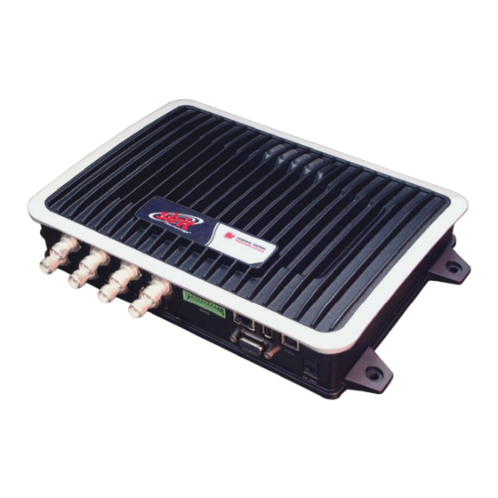
2 3 4 5 6 7 8 9 Reader Overview Reader Overview Reader Hardware 1.1. The INfinity 610 is a multi-protocol, multi-regional Radio Frequency Identification (RFID) System that operates in the 860 – 960 MHz UHF band. INfinity 610 UHF Reader Figure 1 As shown in Figure 1 and Figure 2, this high performance reader supports up to eight Tx/Rx antennas (8x1 monostatic or 4x2 bistatic) and is equipped... - Page 10 3 4 5 6 7 8 9 Reader Overview INfinity 610 Input/Output and Power Panel Figure 2 The INfinity 610 is also equipped with four status indicators located on the top of the enclosure. From left to right, these LEDs provide indication for the following: Number Indication...
-
Page 11: Reader Software
2 3 4 5 6 7 8 9 Reader Overview Reader Software 1.2. The INfinity 610 is shipped with two software applications that you can use to configure and control the reader. Reader Startup Tool (RST) RST is a Microsoft Windows application you install on your computer. With RST, you can view all readers on your network. -
Page 12: Reader Equipment Installation
Any attempt to open the reader housing or modify the reader in any way will void the reader warranty and may violate regulatory requirements. Contact Sirit Customer Support for additional information INfinity 610 Mechanical Dimensions (dimensions in mm) Figure 3 INfinity 610 User’s Guide... -
Page 13: Mounting The Antennas
#8 screws and flat washers. Wood or Metal Wall Mounting To mount the reader to a wood or sheet metal wall, Sirit recommends either #8 x 1 inch wood screws or #8 x 1 inch sheet metal screws and washers. -
Page 14: Electrical Installation
Caution: The INfinity 610 is designed to meet the regulatory requirements in those jurisdictions in which it is offered. Changes or modifications not expressly approved by Sirit Inc for compliance could void the user's authority to operate the equipment. ATTENTION INfinity 610 antenna ports may be susceptible to damage from static discharge or other high voltage. -
Page 15: Connecting The Serial Port
3 4 5 6 7 8 9 Reader Equipment Installation Connecting the Serial Port 2.2.1. The INfinity 610 is equipped with one DB9 type RS-232 serial port for communication up to 115200 Baud. If you are using the serial port for reader communication, connect a serial cable from the COM port on your PC to the serial port on the reader. -
Page 16: Connecting The Antennas
3 4 5 6 7 8 9 Reader Equipment Installation Connecting the Antennas 2.2.4. The maximum antenna cable length is 10 meters. Connect the antenna to antenna port . If you are using additional antennas connect them to Ports 2–8. Antennas can be connected as monostatic, bistatic, or a combination of the two. -
Page 17: Connecting Digital Inputs/Outputs
3 4 5 6 7 8 9 Reader Equipment Installation Connecting Digital Inputs/Outputs 2.2.5. The INfinity 610 is equipped with a general purpose digital input/output (I/O) port that provides four optically isolated 5-24 Vdc input signals and four open-collector output signals. The digital inputs can be used as general purpose inputs or to trigger the reader for tag reading. -
Page 18: Reader Startup Tool (Rst) Software Installation
RST Software Installation Reader Startup Tool (RST) Software Installation Installing RST Software 3.1. The INfinity 610 is delivered with a Microsoft Windows application called Reader Startup Tool (RST). You can use this application to initially configure your reader as well as read and display tag data. Install RST To install RST, load your product CD and double-click the .msi file:... -
Page 19: Windows 7 Setup
RST Software Installation 5 Press After the installation completes, press Next>. Close. Windows 7 Setup 3.2. If you have a Windows 7 operating system, your firewall may block UDP traffic and consequently RST may not discover your readers. Perform the following to configure your system: For Microsoft Firewall Log into your computer as Administrator. -
Page 20: Reader Startup
To begin using your reader, open the RST application. Open RST From your Windows desktop, select: Start→Programs→Sirit→Reader Startup Tool (RST) If this is the first time starting the RST application, you may receive a Windows Security Alert. This warning indicates that the firewall is blocking the RST application. -
Page 21: Initial Reader Setup
RST Software Installation NOTE: Earlier versions of Microsoft Windows™ may not provide the Security Alert popup. IF RST does not discover your reader, check your Windows Firewall/Security settings. Press Unblock. Press on the RST Refresh The RST main page will display any readers currently connected to the network. - Page 22 RST Software Installation Press and enter the Login ( ) and Password. If this is the Next> admin first time configuring your reader, enter: readeradmin. After entering your Login and Password, press Next> INfinity 610 User’s Guide...
- Page 23 RST Software Installation Select the Region and Sub Region and press Next> Custom Setup If your installation type differs from one of the choices shown in the Setup Wizard, you can always customize your setup later using the embedded web interface capability.
- Page 24 RST Software Installation Select the antennas you will be installing and press Next> 10 Estimate the number of tags that will be presented to the reader at any one time and press Next> INfinity 610 User’s Guide...
- Page 25 RST Software Installation Saving Reader Setup Reader setup information should be saved as a profile. In the event that you need to reboot or power down a reader, the reader setup can be quickly reloaded by loading the profile. If you don’t save the reader setup, you can loose the information if the reader is...
-
Page 26: Reader Operation
Reader Configuration Tool (RCT). To operate the reader from RST, perform the following: Open RST From your Windows desktop, select: Start→Programs→Sirit→Reader Startup Tool (RST) Select a specific reader and press Test. The Reader Test Tool (RTT) is displayed. INfinity 610 User’s Guide... - Page 27 Reader Operation Login to the reader. From the pull-down menu select Reader→Login… For administrator login, select . The initial password ( ) is admin readeradmin. See Advanced Setup section to change the password. Verify the Operating Mode is set to .
-
Page 28: Deployed Reader Operation With Rct
Reader Operation Deployed Reader Operation with RCT 4.2. Once your readers are deployed, you can access them directly using the embedded Reader Configuration Tool (RCT). To access a particular reader, perform the following: Enter the reader’s IP address into your web browser or press the button on the main RST page. - Page 29 Reader Operation Advanced Functions →Change Operating Mode Select to verify the reader is in the proper mode. Basic Configuration →Set Tag Protocol Select to verify the reader is configured for the proper tag protocol. System Status →View Tags Press to view tag data. 10 If you need to configure your reader, refer to Chapter 7 –...
-
Page 30: Reader Startup Tool (Rst)
Reader Startup Tool Reader Startup Tool (RST) The Reader Startup Tool (RST) provides an easy-to-use interface for the INfinity 610 configuration and operation functions. This application resides on your Windows based computer and allows you to perform the following: View all readers on the network Launch the to configure a reader Reader Setup Wizard... -
Page 31: Configure Reader With The Setup Wizard
Reader Startup Tool Configure Reader with the Setup Wizard 5.2. The Reader Setup Wizard is used to initially configure your reader for operation. With this application, you can select the following: Installation type Regulatory region and sub-region Protocol Number of antennas Estimated tag volume To initially configure your reader perform the following: From the RST main page, press the... -
Page 32: Customize Discovery Options
Reader Startup Tool Customize Discovery Options 5.3. You can customize the reader discovery options including the Listen Address and Request Multicast Address. Listen Address – Address that RST uses to listen for UDP discovery packets from the reader. This is customizable on the reader. Request Multicast Address –Address used by RST to send out the UDP update request packets. -
Page 33: View Or Change The Reader's Network Settings
Reader Startup Tool View or Change the Reader’s Network Settings 5.4. From the RST main page, press the button. Verify the IP Address, Subnet, and Default Gateway are correct. If Enable DHCP is selected these fields will be locked. If required, change the values. If your reader is running Version 2.0 or later firmware, enter your login and password. -
Page 34: Reader Test Tool (Rtt)
Reader Startup Tool Reader Test Tool (RTT) 5.5. The Reader Test Tool (RTT) is primarily designed for new users to test reader operation and perform a few basic reader functions. With RTT, you can perform the following: Read tags Issue commands to the reader and view the responses Run macros Observe reader events To access the Reader Test Tool, press the... - Page 35 Reader Startup Tool Login to Reader To login to the reader, perform the following: From the pull-down menu, select Reader→Login… Select the type of from the pull down. The default login is Login guest If you need administrator privileges, login as admin Enter your .
- Page 36 Reader Startup Tool Select Protocol You can activate one or more protocols on the INfinity 610 using RST. From >. the pull-down menu, select Active protocols are Protocols→<protocol indicated by Antenna Selection You can select the ports that have antennas connected and which antennas are active.
-
Page 37: Tag Performance Page
Reader Startup Tool Tag Performance Page 5.5.2. ance page is used to test the reader performance. Tag Perform Although it is best suited for reading large populations (hundreds) of tags, as in a multi-antenna portal, it also is useful for range (distance) testing of one tag with one antenna. - Page 38 Reader Startup Tool Performance Information – Number of unique tags in the tag database. Total Unique Tags – Total number of tags read (including repeat reads). Tag Read Count – Cumulative read rate in tags/second since the Cumulative Rate Start button was pressed.
-
Page 39: Tag Management Page
Reader Startup Tool Tag Management Page 5.5.3. page is used for reading individual fields on a single Tag Management tag as well as writing the access password and locking a tag. The Read button will cause the reader to singulate and read a tag in the selected antennas’... -
Page 40: Macros Page
The macros are Macros provided by Sirit or can be written by the end user. Some of the macros provided are dependent on the operating region of the reader. A macro (script or command file) is a text file that contains one or more reader commands. - Page 41 Reader Startup Tool Macro Input sub-window window shows the current script that will be sent to the Macro Input reader when the button is selected. The text in the Send to Reader Macro window can be edited prior to being sent to the reader. Input Macro Output sub-window window is updated after the...
-
Page 42: Event Handling Page
Reader Startup Tool Event Handling Page 5.5.5. page allows you to register for Reader Events. After Event Handling registration, events are displayed with the newest on the bottom and the most recent event will scroll to the bottom of the window. Individual events or a group of events can be registered. -
Page 43: Antenna Settings Page
Reader Startup Tool Antenna Settings Page 5.5.6. page allows you to adjust the power settings for each Antenna Settings antenna. Only the controls for those antennas that are connected are activated. INfinity 610 User’s Guide... -
Page 44: Reader Diagnostics Tool (Rdt)
Reader Startup Tool Reader Diagnostics Tool (RDT) 5.6. The Reader Diagnostic Tool (RDT) is to be used by Sirit trained technicians to troubleshoot and diagnose various reader issues. Administrator login is required. Channel Statistics 5.6.1. page shows details of channel changes. This page is Channel Stats typically used to observe regional behavior. -
Page 45: Alarms
Reader Startup Tool Alarms 5.6.2. ms page is used to capture autonomous alarms generated by the Alar reader during normal operation. The alarms are defined as autonomous reader events for the following namespaces: event.error event.warning INfinity 610 User’s Guide... -
Page 46: Tag Report
Reader Startup Tool Tag Report 5.6.3. The Tag Report page is used to view specific information for each tag singulation. This feature provides detailed attributes of tag singulations such as tag power (RSSI) and on which antenna that tag singulated. Caution: Use of this tool can adversely affect tag reader performance, particularly if many tag fields are enabled. -
Page 47: Spectrum Analyzer
Reader Startup Tool Spectrum Analyzer 5.6.4. The Spectrum Analyzer allows you to examine the spectral composition of the radio waves in your surrounding environment. This feature provides a graphical representation of the current spectral RF noise in units of dBm with a range of 0 to -120 dBm. -
Page 48: Power Ramp Tool
Reader Startup Tool Power Ramp Tool 5.6.5. The Power Ramp Tool determines the minimum power to activate a tag and can help determine tag quality. This activation power level can help determine the read range at various attenuation levels and, for AVI applications, can help determine the "read-zone"... -
Page 49: Embedded Reader Configuration Tool (Rct)
Reader Configuration Tool Embedded Reader Configuration Tool (RCT) The Embedded Reader Configuration Tool (RCT) allows you to access your reader across the internet by entering the reader’s IP address into your web browser. With the RCT, you can fully configure your reader for operation in a variety of applications and environments. -
Page 50: Basic Configuration
Reader Configuration Tool Basic Configuration 6.1. With the Basic Configuration functions you can perform the following: Manage reader profiles Set tag protocols Setup the Ethernet/LAN configuration Setup the serial port Setup digital accessories Setup antennas Set regulatory modes Configuration Page Header 6.1.1. -
Page 51: Manage Profiles
Reader Configuration Tool Save The Save button saves the reader's current configuration to the specified profile. Refer to the Manage Profiles section for detailed information on reader profiles. Manage Profiles This link allows you to list, save, and delete profiles. Refer to the Manage Profiles section for detailed information on reader profiles. - Page 52 Reader Configuration Tool Activate a Profile To activate a previously saved profile, press the button beside the Activate profile name. The selected profile will be loaded into the reader. Delete a Profile To delete a previously saved profile, press the button beside the Delete profile name.
-
Page 53: Set Tag Protocol
Reader Configuration Tool Set Tag Protocol 6.1.3. This page consists of two forms. The first form (top) allows Set Tag Protocol you to select which type of tags the reader will acquire or the type of protocol(s) to utilize on the air interface. Currently, the reader can operate with either ISO18000-6B (ISOB), ISO18000-6C (ISOC), EASAlarm, or any combination of the three. -
Page 54: Setup Ethernet/Lan
Reader Configuration Tool Setup Ethernet/LAN 6.1.4. The Setup Ethernet/LAN page allows you to configure the network interface of the reader. NOTE: Always record the IP, Mac, subnet, and default gateway addresses for your readers and keep this data in a safe location. You can use this data to reconfigure the network in the... -
Page 55: Setup Serial Port
Reader Configuration Tool allow you to specify the host and domain name of the General Settings reader. The Command and Event Ports are also shown and are read-only. You can also select your domain name in this window. allow you to configure the reader’s IP address. If the IPv4/IPv6 Settings reader is to automatically acquire its IP address, subnet mask and default gateway from a DHCP server, select... -
Page 56: Setup Digital Accessories
Reader Configuration Tool Setup Digital Accessories 6.1.6. The Setup Digital Accessories function allows you to configure the Digital Inputs and Outputs on the reader. Digital Input The status of the four digital input values (1–4) can be seen in this window. is not configurable and is shown as . -
Page 57: Setup Antenna/Cables
Reader Configuration Tool Setup Antenna/Cables 6.1.7. This page allows you to configure the reader’s antenna multiplexer sequence ass well as conducted power. For detailed description of each of the antenna and cable variables, refer to Antenna Configuration in Chapter 4 – Reader Behavior of the INfinity 610 Protocol Reference Guide. To configure an antenna, enter the antenna number in the Mux Sequence field. -
Page 58: Set Regulatory Mode (Region)
Reader Configuration Tool Set Regulatory Mode (Region) 6.1.8. This page allows the user to configure the reader to meet the regulatory requirements for the geographic region where the reader is deployed. The sub-region sets the secondary regulatory mode for the geographic region where the reader is deployed. -
Page 59: Advanced Functions
This page allows you to read the current firmware version, upgrade the reader firmware files, or rollback to the previous firmware version. To upgrade reader firmware, enter the name of the Sirit provided firmware file in the field. Use the button to help locate the file. -
Page 60: Import/Export Configuration
Reader Configuration Tool Import/Export Configuration 6.2.2. This page allows you to transfer a reader configuration to or from your host computer. This is useful for configuring a reader to a known state. INfinity 610 User’s Guide... - Page 61 Reader Configuration Tool Import Configuration to Reader Enter the name of a saved configuration file in the field. Configuration file Select the option and press the XML File Transfer Configuration to Reader button to send the profile to the reader. Export Configuration from Reader This function is used to export the current reader settings for later uploading.
-
Page 62: Command Line
Reader Configuration Tool Command Line 6.2.3. This page allows you to directly enter reader commands from your web browser.To directly enter commands from the Command Line Interface (CLI), refer to the INfinity 610 Protocol Reference Guide. INfinity 610 User’s Guide... -
Page 63: Expert Configuration
Reader Configuration Tool Expert Configuration 6.3. The Expert Configuration functions allow you to configure low-level functions within the reader. These functions should only accessed by expert users. Expert configurations include: Setup Version Information NOTE Communication For details on Antennas reader variables, Digital I/O refer to the INfinity 610 Protocol... -
Page 64: Expert Configuration - Tag
Reader Configuration Tool Expert Configuration – Tag 6.3.2. This page allows you to configure how the reader reports tags. The INfinity 610 supports the ability to filter tags or eliminate tags from being reported based on the conditions specified in the filter configuration variables. -
Page 65: Expert Configuration - Version
Reader Configuration Tool Expert Configuration – Version 6.3.3. This page displays the version of reader hardware and reader software within the reader. The version numbers are read-only and will be needed if you contact Sirit for technical support. INfinity 610 User’s Guide... -
Page 66: Expert Configuration - Information
Reader Configuration Tool Expert Configuration – Information 6.3.4. This page allows you to customize the reader’s identity. You can assign each reader a name, description, location, and zone. You can also set how the reader reports timestamps. INfinity 610 User’s Guide... -
Page 67: Expert Configuration - Communication
Reader Configuration Tool Expert Configuration – Communication 6.3.5. This page allows you to customize the reader’s communication parameters. Refer to the Setup Ethernet/LAN and Setup Serial Port sections for additional information. The following figure shows a portion of communication parameters available on the reader. -
Page 68: Expert Configuration - Antennas
Reader Configuration Tool Expert Configuration – Antennas 6.3.6. This page allows you to configure the properties of the reader’s antenna configuration. For detailed description of each of the antenna and cable variables, refer to the Antenna Configuration section in Chapter 4 – Reader Behavior of the INfinity 610 Protocol Reference Guide. -
Page 69: Expert Configuration - Digital I/O
Reader Configuration Tool Expert Configuration – Digital I/O 6.3.7. This page allows you to configure the digital inputs and output behavior. You can set the digital input debounce time (in milliseconds), as well as the input and output pin values. Refer to the INfinity 610 Protocol Reference Guide for detailed information on each of these variables. -
Page 70: Expert Configuration - Modem
Reader Configuration Tool Expert Configuration – Modem 6.3.8. This page allows you to set the reader’s modem control variables. These variables control functions such as EPC link, modulation depth, return link frequency, and others. Refer to the INfinity 610 Protocol Reference Guide for detailed information on each of these variables. -
Page 71: User Application Management
Reader Configuration Tool User Application Management 6.4. This page lists any user applications currently available on the reader and if any applications are running. This page also allows you to upload applications to the reader. Running User Applications – Lists any user applications currently running on the reader. -
Page 72: Change Operating Mode
Reader Configuration Tool Change Operating Mode 6.5. This page allows you to configure the operational mode of the reader. The reader supports the following operational modes: Active Mode - Reader is continuously attempting to singulate tags and automatically reports any singulated tag via an asynchronous event notification on the event channel. -
Page 73: View Tags
Reader Configuration Tool View Tags 6.6. All tags read by the reader are stored in a database on the reader. This page allows you to view the tags in the database as well as change the current Operating Mode (Active or Stand By). Press Start to begin displaying the tag database. -
Page 74: Check Reader Status
Reader Configuration Tool Check Reader Status 6.7. This page allows you to view the reader/system status, CPU utilization, services, and licensed features. This information can be used by Sirit Technical Support to verify reader operation. INfinity 610 User’s Guide... - Page 75 Reader Configuration Tool INfinity 610 User’s Guide...
-
Page 76: Review Logs
Reader Configuration Tool Review Logs 6.8. This page allows you to view the reader logs. These logs can be used by Sirit Technical Support to verify reader operation. The reader logs include: – System level reader operation Reader level Logs –... -
Page 77: Configuring Digital Inputs And Outputs
Configuring Digital I/Os Configuring Digital Inputs and Outputs Digital Inputs 7.1. The digital inputs (DIN1 – DIN4) can be used as general purpose inputs or to trigger the reader for tag reading. Unused or open digital inputs are Digital I/O Module floating inside the reader. -
Page 78: Scan_Trigger_Timer.py
Configuring Digital I/Os scan_trigger_timer.py 7.3.2. This routine monitors the I/O pin. When the pen goes high, the timer is started and the operating mode is set to active. While the timer is running, I/O pin state changes are ignored. When the timer expires, the operating mode is set to standby. -
Page 79: Signal_Read_Crc_Error.py
Configuring Digital I/Os signal_read_crc_error.py 7.3.4. This routine will turn on a digital output if a tag read CRC error is detected. The output pin number can be specified on the command line. If not specified, output pin 1 is used. The output pin will remain high for n ms, where n is either the default of 1000 ms or the value supplied on the command line. -
Page 80: Digital Input Alarm Generation
Configuring Digital I/Os Digital Input Alarm Generation 7.4. The INfinity 610 can be configured to generate an alarm when a digital input is disconnected or sensor failure is detected. The alarm is triggered when the signal level on the digital input stays in the specified state longer than the specified alarm timeout. -
Page 81: Digital I/O Hardware Connection
Configuring Digital I/Os Digital I/O Hardware Connection 7.5. Figure 5 shows a typical sensor/indicator connection to the digital I/Os. External DIO Interface Module An external DIO interface module is available for the INfinity 610. See the Appendix in this User’s Guide for more information. -
Page 82: Specifications
Specifications Specifications Reader Specifications 8.1.1. Frequency 902 – 928 MHz RF Power 10 mW – 1W conducted (30 dBm) Power Consumption 10W (typical while idle) 18W (typical at 1W conducted output power) 20W (maximum at 1W conducted output power) Connections RS-232, Digital I/O, Ethernet LAN Input Voltage 24 Vdc... -
Page 83: Environmental Specifications
Specifications Environmental Specifications 8.1.2. Operating Temperature -4° F to 131° F (-20° C to 55° C) Storage Temperature -40° F to 185° F (-40° C to 85° C) Maximum Shock 1 foot (0.3 meter) drop to any corner Relative Humidity 5% to 95% non-condensing Case Material Aluminum... -
Page 84: Digital Input/Output Specifications
Specifications Digital Input/Output Specifications 8.1.5. Connector Phoenix Contact PN 1881422 Input 5 to 24 Vdc, 1 to 5 mA, Optically Isolated Output Open Collector (3 to 40 V, 100 mA Max) Pin 1 – Digital Common Voltage Reference for DIN1/DIN2 Signals Pin 2 –... -
Page 85: Infinity 610 Antenna Specifications
RF field in excess of Health Canada limits for the general population; consult Safety Code 6, obtainable from Health Canada’s website at www.hc-sc.gc.ca/rpb. Optional Sirit supplied antennas are for indoor use only. INfinity 610 User’s Guide... -
Page 86: Safety Instructions
The INfinity 610 is designed to meet the regulatory requirements in those jurisdictions in which it is offered. Changes or modifications not expressly approved by Sirit Inc for compliance could void the user's authority to operate the equipment. INfinity 610 User’s Guide... -
Page 87: In610 Digital Input/Output Interface Module
NOTE: The DIO Interface Module may not be available for some models. Please contact your Federal Signal/Sirit Representative for availability. The Sirit DIO Interface Module provides an easily accessible interface to the reader’s four digital inputs and four digital outputs. Screw terminals provide secure signal connections and eight LEDs indicate I/O activation. -
Page 88: Digital Inputs
Appendix A IN610 DIO Interface Module Digital Inputs A.1. The digital inputs (Terminal 1–Terminal 4) can be used as general purpose inputs or to trigger the reader for tag reading. Unused or open digital inputs are pulled high to +15 Vdc inside the reader. The DIO interface module has an LED provided in series with each digital input line that lights when the input is activated by an external source. -
Page 89: Connecting External Switches And Indicators
Appendix A IN610 DIO Interface Module ATTENTION INfinity 610 antenna ports may be susceptible to damage from static discharge or other high voltage. Use proper Electrostatic Discharge (ESD) precautions to avoid static discharge when handling or making connections to the INfinity 610 reader antenna or communication ports. Equipment failure can result if the antenna or communication ports are subjected to ESD. - Page 90 Appendix A IN610 DIO Interface Module If using a multiple element light stack, such as the Allen Bradley 855T, connect the device as shown in the following figure (B). In the following example, the four-element light stack (Allen Bradley 855T) must be installed with the common (0) connected to +15V and each element (1, 2, 3, 4) connected to the appropriate output.
-
Page 91: Usb Port Setup
Appendix B USB Port Setup USB Port Setup The INfinity 610 is equipped with two USB 2.0 ports: USB Type B – Provides connectivity to the INfinity 610 console. This connection is used to send commands and receive responses and is typically connected to your server. - Page 92 Appendix B IN610 DIO Interface Module Install from a list or specific location (Advanced) Select and click Next Setup the path to the driver and click Next INfinity 610 User’s Guide...
- Page 93 Appendix B USB Port Setup Since the Gadget Serial driver has not passed the Windows Logo testing, a warning appears. Press Continue Anyway INfinity 610 User’s Guide...
- Page 94 Appendix B IN610 DIO Interface Module Once the installation is complete, press Finish Open the Device Manager and verify the driver was installed correctly as shown in the following: INfinity 610 User’s Guide...
- Page 95 Appendix B USB Port Setup After driver installation, start and configure the new port PuTTY as follows: 10 The Command Line Interface should appear. INfinity 610 User’s Guide...
-
Page 96: Windows 7 Driver Installation And Setup
Appendix B IN610 DIO Interface Module Windows 7 Driver Installation and Setup B.2. To map the Gadget Serial driver on a Windows 7 machine, perform the following: Connect the reader to your computer using an A-B USB cable. If the Gadget Serial driver is already mapped to a COM port, the following will appear: If the driver is not mapped, the warning... - Page 97 Appendix B USB Port Setup Right click the device and click Properties Select the tab. Hardware Click the button. Properties INfinity 610 User’s Guide...
- Page 98 Appendix B IN610 DIO Interface Module Click the button. Change Settings INfinity 610 User’s Guide...
- Page 99 Appendix B USB Port Setup Click the tab. Driver 10 Click the Update Driver button. INfinity 610 User’s Guide...
- Page 100 Appendix B IN610 DIO Interface Module 11 Select Browse my computer for driver software 12 Select Let me pick from list of device drivers on my computer 13 Uncheck the checkbox. Show compatible hardware 14 Click the and click the button.
- Page 101 Appendix B USB Port Setup 15 Create a directory called: c:\windows\system32\drivers\Sirit 16 Copy the files gserial.inf and win7_usbser.sys from the USBWinDrivers directory on your Documentation CD into the new directory. 17 After copying files, rename win7_usbser.sys to usbser.sys. 18 Go to c:\windows\system32\drivers\Sirit 19 Click the file gserial.inf and click...
- Page 102 Appendix B IN610 DIO Interface Module 21 Click Next 22 Select Install this driver software anyway INfinity 610 User’s Guide...
- Page 103 Appendix B USB Port Setup 23 Press Close 24 The driver is now mapped to COM5 and is ready for use. INfinity 610 User’s Guide...
-
Page 104: Disposal Of The Infinity 610 Reader
Appendix C Disposal of the INfinity 610 Reader Disposal of the INfinity 610 Reader Prior to disposing of the INfinity 610 Reader, the battery must be removed. The battery used in the Infinity 610 is a Lithium / Manganese Dioxide (Li/MnO2) type. - Page 105 Appendix B Disposal of the INfinity 610 Reader Remove the two (2) retaining nut/screws on each side of the serial connector. Left out the main circuit board and turn over. Locate the battery on the upper right quadrant of the board. Battery 10 Use a small flat-blade screwdriver to push the battery out of the holder.
-
Page 106: C Disposal Of The Infinity 610 Reader
Appendix C Disposal of the INfinity 610 Reader This page intentionally left blank. INfinity 610 User’s Guide... - Page 107 This page intentionally left blank. INfinity 610 User’s Guide...
- Page 108 INfinity 610 User’s Guide...
Need help?
Do you have a question about the INfinty 610 and is the answer not in the manual?
Questions and answers