Table of Contents
Advertisement
RCB600, MCB600
User Manual
The RCB and MCB series user manual has been prepared
by the Roal Electronics design team to assist qualified engineers
in correctly implementing the products and to achieve the best reliability and performance.
At time of print, the information contained in this document is believed to be correct and accurate. However, specifications are subject to change
without prior notice and Roal Electronics will not be liable for any damage caused as a result of the information within this document. For
continued product improvement, please report any errors contained in the document to Roal Electronics SpA.
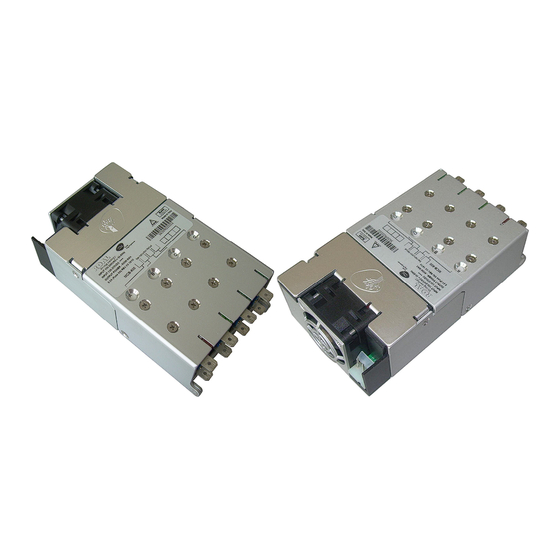
RCB600 and MCB600 series overview
RCB600
MCB600 S
AND
The RCB600 and MCB600 switch mode power supply series offers truly unrivalled power density, providing 600 W at 25 W/in
in a 5" x 3"x 1U package. They are the ultimate power solutions for system designers as they address the pressing demands
for more power within less space. Providing multiple isolated outputs, the series carry full UL60601 (MCB600) and UL60950 2
edition (RCB600) safety approvals.
The basic system consists of an input module together with up to four fully isolated output modules, all supplied with advanced
remote voltage and current programming functionality as standard.
The input module delivers up to 600 W of output power and has 4 slots, each capable of separately delivering up to 150 W. A
5 V, 200 mA medically isolated bias supply together with an AC mains signal (AC_OK) and a global inhibit signal (GINH) that
can disable all outputs simultaneously, comes as standard on all models.
A built in fan, which speed is automatically controlled, ensures the unit proper cooling in any operating condition maintaining
at minimum fan RPM and, in turn, acoustic noise.
Output modules are currently available in single output types with models covering voltage ranges from 1.5 V to 58 V and
currents up to 25 A. All outputs can be connected in parallel or in a series resulting in a voltage range of up to 232 V and a
maximum current of up to 100 A from a single chassis.
By selecting the correct output modules, a custom power solution can be configured in a few minutes. This instantly available
custom solution offers industry leading power density, total system efficiencies of up to 89% and suits all types of applications
including industrial, medical, aerospace, military and telecoms.
O
ERIES
VERVIEW
3
nd
Advertisement
Table of Contents

Related Manuals for roal RCB600


Summary of Contents for roal RCB600
-
Page 1: Rcb600 And Mcb600 Series Overview
At time of print, the information contained in this document is believed to be correct and accurate. However, specifications are subject to change without prior notice and Roal Electronics will not be liable for any damage caused as a result of the information within this document. For continued product improvement, please report any errors contained in the document to Roal Electronics SpA. -
Page 2: Table Of Contents
ONTENTS RCB600 and MCB600 series overview ................. 1 Models and ordering information................3 Installation Notes ....................4 Theory of operation ....................5 Input module operation .................... 6 Signalling ....................... 9 Output module operation ..................11 Advanced output module features ................14 Seriesed outputs ....................17 Outputs in parallel configuration ................18... -
Page 3: Models And Ordering Information
ONFIGURATIONS AND RDERING NFORMATION Models and ordering information The RCB/MCB600 part numbering system is easily comprehensible following the scheme in the table below. A power unit part number can also be easily accessed through the descriptive label placed on its top surface (see picture below). -
Page 4: Installation Notes
To prolong the life of the unit, use in dust free environment. If units are damaged during transit, contact your sales agent or Roal Electronics and DO NOT apply power to the unit. Always use adequately sized cables and ensure good crimp connections. -
Page 5: Theory Of Operation
HEORY OF PERATION Theory of operation The diagram below outlines the topology and major internal components of a fully assembled system. Four output slots are provided and can be populated by any combination of output modules (OP-A, OP-B, OP-C, OP-D). The remaining components in the block diagram are housed in the input module. -
Page 6: Input Module Operation
PERATION Start-up and shut-down The RCB600 and MCB600 input modules operate from a universal input voltage range and start automatically upon application of adequate AC mains voltage (>84 V ). After a short delay, the global “+5V bias” supply starts and the “ACOK” signal goes high to indicate that the mains voltage is present and input stage is operating correctly. - Page 7 Power De-rating The RCB600 and MCB600 units must always be operated within its stated operating limits. Equipment manufacturers and other users must take appropriate de-ratings into account at all times when specifying a unit for the intended application. If in doubt, contact your sales representative or Roal Electronics for assistance.
- Page 8 An estimate of the efficiency for any particular system may be obtained from these graphs using the procedure outlined in the example below. Example: Estimate the efficiency of an RCB600-AABC, at 160 V input and 100 W load on each output? Define load efficiencies for each output module at specified load and 220 V...
-
Page 9: Signalling
IGNALS Signalling To reduce cabling in the end system, all major input and output signals and the global +5V bias supply are wired to a single signals circuit that is accessed through the connector (J2) located at the output side of the chassis as shown in the diagram below. - Page 10 Power Good signals _ PG1-PG4 (Output) Each output module provides a power good (PG) signal to indicate when the output voltage is above approximately 90% of the preset voltage for that module. Each PG signal on an output module is internally connected through an opto-isolator to the signals circuit, which buffers the signal through a PNP transistor with a 10 kΩ...
-
Page 11: Output Module Operation
UTPUT ODULE PERATION eration Power profile The power profile diagram below is a voltage/current plot that together with the associated table provides details of the main features of the currently available output modules. Output voltage adjustment Each output can be adjusted within the range as described in the table above or in the datasheet. Voltage adjustment can be achieved by two methods;... - Page 12 Reverse Current Protection (RCP) The standard output modules use synchronous rectification in the output stages to achieve high efficiency and as a result the outputs can both source and sink current. The sink current is internally limited to approximately -6% of the maximum rated current.
- Page 13 Ripple and Noise The ripple and noise figures stated in the datasheet are defined based on a standard measuring method. To obtain the same results the same test setup must be used and care must be taken to eliminate any parasitic noise pickup. The diagram below shows details of the setup and also sources of noise pickup.
-
Page 14: Advanced Output Module Features
DVANCED UTPUT ODULE EATURES Advanced output module features Remote voltage programming (External voltage control) The output voltage of the module can be adjusted using an external voltage source connected between the COM and V control pins on the signals connector (J5) as shown below. In this configuration the output voltage will follow the equation below, ((1.8 - V ) / 0.6), where V... - Page 15 Remote current programming (External voltage control) The output current limit of the module can be reduced using an external voltage source connected between the COM and pins on the signals connector (J5) as shown below. In practice, this also means that the output can be used as a control modulated or constant current source.
- Page 16 when using the I signal to measure the output current as loading the I signal, even with microamps can cause the control control current limit to be reduced. If it is required to measure the output current and adjust the output current limit simultaneously, this can be achieved by using a clamp circuit instead of a voltage source to adjust the current limit, while continuing to use an amplifier to measure the output current.
-
Page 17: Seriesed Outputs
UTPUT ODULES IN ERIES Seriesed outputs RCB/MCB output modules of the same type can be seriesed in any number to achieve higher output voltages, even across multiple chassis. The following instructions must be followed for output modules configured in this manner. WARNING! Energy and voltage hazards may arise when individual modules are seriesed. -
Page 18: Outputs In Parallel Configuration
UTPUTS IN ARALLEL ONFIGURATION Outputs in parallel configuration RCB/MCB output modules of the same type can be paralleled in any number within the same chassis to achieve higher output currents. WARNING! Energy hazards may arise when individual modules are paralleled. See the Safety section for more details. - Page 19 Failure to provide such protection may result in damage to the units. Consult Roal Electronics for details on how best to implement such applications. Where units are paralleled across multiple chassis, the outputs in each chassis will not be synchronised and the peak-to-peak...
- Page 20 Parallel remote sensing Remote sensing can be used as normal with paralleled modules. The sense lines (S+ and S-) from each of the output modules should be connected together, S+ to S+, and S- to S- as shown below. This should be done close to the power supply output and a single pair of cables brought from these sense lines to the load.
- Page 21 Paralleled remote voltage/current adjust The simplest way to achieve remote voltage/current programming with paralleled outputs is to operate the modules in share parallel mode. Follow the procedure outlined earlier to configure the outputs in share parallel mode and once configured in this mode, all the V and COM pins can be connected together.
-
Page 22: Mechanical Dimensions And Mounting
ECHANICAL IMENSIONS AND OUNTING Mechanical dimensions and mounting Nominal Units Specifications Details Dimensions Height is 1U 77.7 x 136.3 x 41.0 3.06 x 5.36 x 1.61 Weight Chassis + Input 0.99 Output modules 0.10 Mounting Bottom or side mounting through M4 screws SCREWS MH1, MH2, MH3, MH4, MH5 Screw type... -
Page 23: Connectors
ECHANICAL ONNECTORS AND SSIGNMENT Connectors PIN ASSIGNMENT Circuit Details Neutral Earth Live Power Good Slot #1 Inhibit Slot #1 Power Good Slot #2 Inhibit Slot #2 Power Good Slot #3 Inhibit Slot #3 Power Good Slot #4 Inhibit Slot #4 Global Inhibit AC OK +5V 200mA, Bias Supply... -
Page 24: Configuring Your Power Supply
Output power modules (OP-A, OP-B, OP-C, OP-D) may be added, replaced or moved by strictly following the sequence of operations described here below. Please contact ROAL Electronics or your distributor for assistance in configuring your power supply. Step 1: Remove the AC input line connection and all other connections from the power supply. Remove the unit from the system where it could be applied. - Page 25 Step 3: Each output module (OP) or blanking plate (BP) is secured to the pivoted lid through a couple of screws. A power supply, however configured, does have four pairs of screws visible on the upper surface of the lid. When re-configuring a power supply only remove the screws that hold an OP while living tightened BP’s ones.
- Page 26 Step 5: With the lid properly rotated, the OPs can be removed and replaced as required. In case the power supply is fully populated by four OPs (one output module for each slot), to remove them start with slot #1. Hook one finger underneath the output module heat-sink, near the back, and lift it out while holding down the main chassis.
- Page 27 A blanking plate must always be used whenever a slot does not contain an output module. Any blanking plate should be secured to the lid before closing it. To facilitate operations, the BPs should be assembled before the OPs. As evidence of power unit proper closing, output modules PCBs must be properly housed in the notches and in the slots of the chassis and cover respectively, mechanical parts and screws holes must be aligned without exerting any effort.
- Page 28 Step 5: Insert all the screws and tighten them as required in the table above. Always use the appropriate tooling (Pozidriv point size:1) and do not over tighten. WARNING! Do not apply power to the power supply before replacing the lid and securing all the screws. Never remove the cover secured on the input side of the chassis.
-
Page 29: Safety
Care should be taken to ensure liquid or metal shavings do not enter the power supply as this can cause a fire hazard. The power supply does not contain any user serviceable parts and should be returned to Roal Electronics for repair. -
Page 30: Emc Compliance
Where cables must enter or exit the enclosure, good high frequency 100 nF decoupling capacitors of sufficient voltage rating should be connected to the cables as close to the entry/exit point as possible. For further details or assistance contact Roal Electronics. -
Page 31: Reliability
Reliability The RCB/MCB600 series has undergone extensive testing, including HALT and Environmental testing. Reliability data is collected on an ongoing basis. Please contact ROAL Electronics or your distributor for the most up-to-date reliability data. Roal Electronics, S.p.A. may change product specifications and accordingly the information presented in this document.
Need help?
Do you have a question about the RCB600 and is the answer not in the manual?
Questions and answers