Advertisement
7610.724.11B
10/01
INSTRUCTION MANUAL
Contents
1.0 INSTALLATION ....................................................... 2
2.0 OPERATION ........................................................... 3
3.0 MAINTENANCE ..................................................... 4
TROUBLESHOOTING GUIDE ........................................... 6
SPECIFICATIONS ......................................................... 7-8
ELECTRICAL SCHEMATICS .............................................. 9
DIMENSIONS AND WEIGHTS ................................... 10-12
PARTS LIST ............................................................. 13-14
WARRANTY ................................................................. 16
General Safety Information
1.
Pressurized devices
This equipment is a pressure containing device.
• Do not exceed maximum operating pressure as
shown on equipment serial number tag.
• Make certain equipment is depressurized before
servicing.
2.
Electrical
This equipment requires electricity to operate.
• Install equipment in compliance with national and
local electrical codes.
• Standard equipment is supplied with NEMA 1
electrical enclosures and is not intended for
installation in hazardous environments.
• Disconnect power supply to equipment when per-
forming any electrical service work.
3.
Breathing air
• Air treated by this equipment may not be suitable
for breathing without further purification. Refer to
OSHA standard 1910.134 for the requirements for
breathing quality air.
SERVICE DEPARTMENT: (800) 475-5660
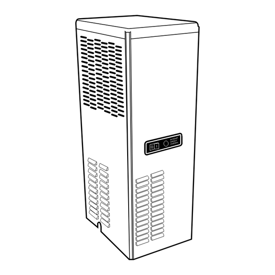
PROdry
TM
High Inlet
Temperature
refrigerated
compressed air
dryers
Advertisement
Table of Contents

Summary of Contents for Devair PROdry
-
Page 1: Table Of Contents
DIMENSIONS AND WEIGHTS ........10-12 PARTS LIST ............. 13-14 WARRANTY ..............16 General Safety Information Pressurized devices PROdry This equipment is a pressure containing device. • Do not exceed maximum operating pressure as shown on equipment serial number tag. High Inlet •... -
Page 2: Installation
1.0 INSTALLATION 1.1 Location 2. Location in the compressed air system Maximum working pressure - 175 psig, A. Air compressor intake - Locate air compressor so that contaminants potentially harmful to the dryer are not 12.3 kgf/cm . Do not exceed unit’s Maximum Working Pressure. -
Page 3: Operation
2.0 OPERATION D. Maximum flow capacity 1. For dryers without an aftercooler installed upstream NOTE: Installations above 6000 feet, 1825 meters /min) @ 180 °F, 82°C inlet Flow capacity in scfm (m Unit is adjusted to operate in altitudes up to 6000 feet, temperature, 160 °F, 71°C inlet pressure dew point, 1825 meters. -
Page 4: Maintenance
3.0 MAINTENANCE 3.3 Replace separator/filter element yearly or DRYER IS A PRESSURE CONTAINING DEVICE. more often if pressure drop across the dryer DEPRESSURIZE BEFORE SERVICING. is excessive. 3.1 Ambient air filter - Clean accumulated dust and dirt A. Shut-off compressed air supply to the dryer and from ambient air filter monthly or more often if air flow across the condenser is impeded. - Page 5 3.4 Automatic condensate drain H. After making sure that O-ring and wave spring inside top of bowl are in place, reassemble bowl to head. • Check daily to be sure automatic drain is NOTE: Make certain O-ring is generously lubricated discharging.
-
Page 6: Troubleshooting Guide
TROUBLESHOOTING GUIDE SYMPTOM POSSIBLE CAUSE(S) CORRECTIVE ACTION A) Water downstream of dryer 1. Residual free moisture remaining in Blow out system with dry air downstream pipelines 2. Air by-pass system is open Check valve positions 3. Inlet and Outlet connections are Check for correct connection reversed 4. -
Page 7: Specifications
SPECIFICATIONS - Models 20 thru 75 Operating Conditions 60 / 50 Hz Rated Capacity scfm 20 / 17 25 / 21 35 / 27 50 / 50 75 / 61 60 / 50 Hz @125 psig, 8.8 kgf/cm /min 0.57 / 0.48 0.71 / 0.59 0.99 / 0.76 1.42 / 1.42... - Page 8 SPECIFICATIONS - Models 100 and 125 Operating Conditions 60 / 50 Hz Rated Capacity scfm 100 / 83 125 / 104 60 / 50 Hz @125 psig, 8.8 kgf/cm /min) (2.83 / 2.35) (3.54 / 2.95) °F (82°C) l n I °F (2-43°C) 60 / 50 Hz Pressure Drop @...
-
Page 9: Electrical Schematics
ELECTRICAL SCHEMATICS Models 20 thru 75 - All Voltages Only Models 50 and 75 - 115-1-50/60 Only Models 50 and 75 - 115-1-50/60 NEMA 5-20P PLUG 20A, 125V REFRIGERANT COMPRESSOR HIGH TEMPERATURE CONDENSER FAN MOTOR Models 100 and 125 - All Voltages LEGEND LINE SW - On/Off Switch... -
Page 10: Dimensions And Weights
DIMENSIONS AND WEIGHTS Models 20, 25, 35 257 mm 6 mm Model Weight 79 lbs (36 kg) 80 lbs (36 kg) 81 lbs (37 kg) 5.1/16 " 128 mm 718 mm 317 mm 1.9/16 " 1" 25 mm 40 mm 21 mm 5 mm 105 mm... - Page 11 DIMENSIONS AND WEIGHTS Models 50 and 75 425 mm Model Weight 6 mm 150 lbs (68 kg) 155 lbs (70 kg) 933 mm 8 7/16" 213 mm 419 mm 1.1/2" 25 mm 38 mm 15 1/4" 387 mm 21 mm 5 mm 117 mm 429 mm...
- Page 12 DIMENSIONS AND WEIGHTS Models 100 and 125 Model Weight 187 lbs (85 kg) 189 lbs (86 kg) 1" 1"...
-
Page 13: Parts List
PARTS LIST PARTS DESCRIPTION Separator *Separator/Filter Cartridge E9-16 E9-16 E9-16 E9-20 E9-24 t l i Inlet (Compressed Air) Strainer l n i Electrical Light, Fault (amber) 6350.451.10 6350.451.10 6350.451.10 6350.451.10 6350.451.10 115/1/60 Light, Fault (amber) 6350.451.11 6350.451.11 6350.451.11 6350.451.11 6350.451.11 220-240/1/50 Cord Set 03.7133-10... - Page 14 PARTS LIST PARTS DESCRIPTION Separator *Separator/Filter Cartridge E9-24 E9-24 t l i l n i Electrical 230/1/60 Capacitor, run 5910.103.50 5910.103.50 220-240/1/50 5910.103.13 Capacitor, run 5910.103.13 Switch, fault light w/conn. 03.7419-03 03.7419-03 Condenser Fan Refrigeration System 230/1/60 Compressor 4130.106.73 4130.106.73 220-240/1/50 4130.106.74 Compressor 4130.106.74...
- Page 15 NOTES...
-
Page 16: Warranty
All decisions by Devair Inc. with regard to this policy shall be final. Devair will not be responsible for any claimed defective materials returned other than in accordance with this statement of policy or without our prior authorization.


Need help?
Do you have a question about the PROdry and is the answer not in the manual?
Questions and answers