Table of Contents
Advertisement
Quick Links
Download this manual
See also:
User Manual
Advertisement
Table of Contents

Subscribe to Our Youtube Channel
Related Manuals for Sony Vaio PCG-F420

Summary of Contents for Sony Vaio PCG-F420
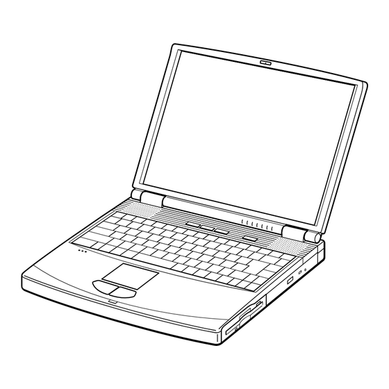
- Page 1 PCG-F420/F480/F490 SERVICE MANUAL US Model Canadian Model S400 Illust : PCG-F490 NOTEBOOK COMPUTER 9-872-058-11...
- Page 2 Caution Markings for Lithium/Ion Battery - The following or similar texts shall be provided on battery pack of equipment or in both the Sony and VAIO are trademarks of Sony. Intel logo and Intel Inside operating and the service instructions.
-
Page 3: Table Of Contents
TABLE OF CONTENTS Section Title Page CHAPTER 1. REMOVAL 1-1. Flowchart ................. 1-1 1-2. Main Electrical Parts Location Diagram ......1-1 1-3. Removal ................1-2 1. Hinge Cover ..............1-2 2. Keyboard Unit, Palm Rest Assy, Hood Keyboard Assy ... 1-2 3. -
Page 4: Chapter 1. Removal
CHAPTER 1. REMOVAL 1-1. Flowchart BEZEL DISPLAY INVERTER HOUSING HOUSING UNIT ASSY ASSY ASSY ∗P 1-7 ∗P 1-7 ∗P 1-7 ∗P 1-7 (P 1-9) (P 1-9) (P 1-9) (P 1-9) HOOD POWER DVD-ROM DISPLAY MBX-30 KEYBOARD PALM REST KEYBOARD DRIVE ASSY ASSY BRACKET... -
Page 5: Hinge Cover
1-3.Removal 1. Hinge Cover 2Hinge Cover 1Door I/O 2Hinge Cover 2. Keyboard Unit, Palm Rest Assy, Hood Keyboard Assy 1M2X4 Special Head 2Pull it up sliding it 3M2X4 Special Head to the right. Keyboard Unit Hood Keyboard Assy 6+B (M2X18) 7Pull it to the front slightly and raise to remove it. -
Page 6: Display Assy, Dvd-Rom Drive
3. Display Assy, DVD-ROM Drive 5M2X6 Special Head Display Assy (X2) 5M2X6 Special Head 5M2X6 Special Head 6M2.6 Cross (Hole) Bind 7M2.6 Cross (X2) (Hole) Bind 1Bolt (M2X2) Spring 4Screw (M2), 0 Number P3 Kind 7M2.6 Cross (Hole) Bind (X2) DVD-ROM Drive CD-ROM Drive 2M2X4 Special Head... -
Page 7: Swx-41 Board, Latch Detector Unit, Pws-8 Board, Nickel Hydrogen Battery
5. SWX-41 Board, Latch Detector Unit, PWS-8 Board, Nickel Hydrogen Battery PWS-8 Board CN6006 3M2X4 Special Head (X3) 1M2X4 Special Head 4PWS-8 Board PWS-8 Board CN6001 2Latch Detector Unit SWX-41 Board CN5101 2SWX-41 Board 5Nickel Hydrogen Battery 6. PC Card Connector, IFX-86 Board, CNX-81 Board, P3 Assy (CPU Module), MBX-30 Board 0+PS 2X4 (X3) P3 Assy 1M2X6 Special Head(X4) -
Page 8: Speaker Unit, Swx-39 Board
7. Speaker Unit, SWX-39 Board 3M2X4 (X2) 2M2X4 (X7) SWX-39 Board Speaker Unit CN301 SWX-39 Board CN302 SWX-39 Board 3M2X4 (X2) SWX-39 Board CN303 Speaker Unit Hood Keyboard 8. SO-DIMM 1M2X4 Special Head 2DIMM Door Removal of SO-DIMM a → b Confidential PCG-F420/F480/F490 (UC) -
Page 9: Attaching The Thermal Sheet
9. Attaching the Thermal Sheet Attach the thermal sheet (20 × 11 mm) to the heat sink of the P3 assembly (CPU module) to be used with the PCG-F420/F480/ F490. Because the heat dissipation effect of the thermal sheet (thermal conductivity sheet) changes depending on the position where it is attached, prepare the following [Thermal sheet attachment tool] to attach the thermal sheet. -
Page 10: Lcd Section (F480/F490 Model)
10. LCD Section (F480/F490 MODEL) 1. Bezel Housing Assy, LCD Unit (15 inch) 1Side (15) Screw Cover (X3) 2+P M2X3 (X3) 3Cover Screw Shaft Bezel Housing Assy 4+P 2.6X6 Lock Precision Type3 : claw part 3Cover Screw 2+P M2X3 (X3) Shaft 1Side (15) Screw Cover (X3) -
Page 11: Inverter Assy, Lcd Cable, Display Housing Assy
2. Inverter Assy, LCD Cable, Display Housing Assy LCD Cable 2M2X4 Inverter Bracket 3M2X4 Special Head Special Head (X2) Inverter Bracket Inverter Assy Inverter Assy Display Housing Assy Confidential PCG-F420/F480/F490 (UC) -
Page 12: Lcd Section (F420 Model)
11. LCD Section (F420 MODEL) 1. Bezel Housing Assy, LCD Unit (13 inch), Display Housing Assy, Inverter Assy, Hinge Left, Hinge Right 1Upper Screw Cover Bezel Housing Assy 2M2X4 Special Head 1Lower Screw Cover : claw part 2M2X4 1Upper Screw Cover Special Head 2M2X4 Special Head 1Lower Screw... -
Page 13: Lcd Cable
2. LCD Cable LCD Cable Confidential PCG-F420/F480/F490 (UC) 1-10 (END) -
Page 14: Chapter 2. Self Diagnostics
CHAPTER 2. SELF DIAGNOSTICS 2-1. Required Tools and Peripheral Devices Tools and Peripheral Devices Test Items Serial Loopback Tool Serial Port (COM) test Specified Loopback Tool (Refer to next page.) Parallel Loopback Tool Parallel Port (printer) test Specified Loopback Tool (Refer to next page.) V.34 Modem and Line Simulator Modem test PC Card Tester... - Page 15 [Reference] On Serial/Parallel Loopback Tool • The serial loopback tool and the parallel loopback tool are necessary for diagnostics of the serial communication line and the parallel communication line. Fabricate the serial loopback tool and the parallel loopback tool locally referring to the connection diagrams shown below.
-
Page 16: Tools And Peripheral Device Connection
2-2. Tools and Peripheral Device Connection System Connection Diagram 2Parallel 1Serial loopback tool loopback tool Serial I/F Serial Parallel output output Modem 5,qsPCG-N505, XR series 3Transmission line simulator IrDA PPK Button send/ receive port-1394 Power SW Phone jack CD-ROM 4PC card tester 9Diagnostics DVD-ROM CD-ROM media... -
Page 17: How To Start The Diagnostics
2-3. How to Start the Diagnostics Precaution: The supplied floppy disk containing the diagnostics program can be damaged because it will be written the Log and used as FDD read-write test. Be sure to make a backup of the diagnostics floppy disk and use a backup disk for diagnostics. -
Page 18: Short Descriptions Of The Test Items
21. Aging (Short time) 22. Aging (Long time) The following tests are performed using Windows 98. A. Audio test group (1) Audio test (MIC test) (2) Audio test (Speaker test) Modem loopback test 2-4-2. Short Descriptions of the Test Items 1. - Page 19 6. Touch pad test Tests the touch pad. Start pressing the keyboard surely from an end of a keyboard. The Fn key is disabled. Press “Fn+End” instead. 7. LED test Check that the LEDs start illuminating from the left of the LEDs. 8.
- Page 20 19. Aging (Short time) HDD test Executes the memory and main system tests repeatedly including the HDD test. It takes about four hours. Contents of HDD are destroyed when this test is performed. 20. Aging (Long time) HDD test Executes the memory and main system tests repeatedly including the HDD test. It takes about ten hours.
-
Page 21: Chapter 3. Block Diagram
33MHz CLK GEN PCI BUS 100MHz C9716 Serial USB 0 DSUB-9 PIRQD* 100-pin PIRQC* PORT0 i.LINK Audio PIRQD* (USB) SONY YAMAHA Parallel IFX-86 CXD3222AR DSUB-25 YMF744B DS-1S FUJI MODEM USB 1 Dev# 8 MD8405E South Bridge Dev# 9 CONEXANT PORT1... -
Page 22: Chapter 4. Frame Harness Diagram
CHAPTER 4. FRAME HARNESS DIAGRAM NICKEL HYDROGEN BATTERY 2nd BATTERY PACK PWS-8 (Option) SWX-41 Side-B CNX-82 P3 ASSY Side-A CN201 CN202 CN6001 CN6002 PC 100 SO-DIMM MODULE CN5101 CN6006 TOUCH CN6005 BATTERY CN 151 DIMM CN6003 PACK FDD BAY Side-A Side-B DRIVE CN 152 DIMM... -
Page 23: Chapter 5. Exploded Views And Parts List
CHAPTER 5. EXPLODED VIEWS AND PARTS LIST NOTE: The components identified by mark 0 or • The mechanical parts with no reference number in the dotted line with mark 0 are critical for safety. exploded views are not supplied. Replace only with part number specified. •... -
Page 24: Main Section
5-1. Main Section Ref.No. Part No. Description Ref.No. Part No. Description X-4622-445-3 ASSY BOTTOM 4-644-665-01 INSULATOR MODEM B 4-640-837-12 DOOR BATTERY * 67 4-641-366-02 LABEL I/O A-8056-756-A RO-33 COMPLETE PWB 4-641-629-01 INSULATOR FDD (or RO-36 COMPLETE PWB) 4-641-763-01 LABEL FD 1-542-331-11 MICROPHONE UNIT * 70 4-641-850-01 SPRING (CD-ROM), PLATE... - Page 25 Ref.No. Part No. Description 4-641-726-41 SCREW (M2), SPECIAL HEAD 4-644-518-01 SCREW (M2X18), +B 4-644-899-01 SCREW (M2), 0 NUMBER P3 KIND 4-639-112-01 SCREW M2X4 4-644-402-01 SCREW (MBX) 4-641-656-02 SCREW (M2.5), 0 PLATE P 4-644-402-11 SCREW (MBX) 4-641-726-11 SCREW (M2), SPECIAL HEAD 4-640-694-41 BOLT (M2), SPRING 7-685-106-19 SCREW +P 2X10 TYPE2 NON-SLIT 4-642-229-01 (F420)...TAPPING (B 2X)
-
Page 26: Lcd Section (F480/F490 Model)
5-2. LCD Section (F480/F490 Model) Ref.No. Part No. Description Ref.No. Part No. Description 1-475-809-31 INVERTER UNIT 4-641-726-41 SCREW (M2), SPECIAL HEAD X-4622-447-2 HINGE LEFT 15G 4-641-726-11 SCREW (M2), SPECIAL HEAD X-4622-416-4 ASSY HOU, BEZEL 15X (UC) 4-642-761-01 +P M2X3 LOCK 4-637-902-41 LATCH 4-644-165-01 SCREW (M2.6X4), 0 PLATE P1 MAIN 1-418-574-21 LCD-UNIT (15.0"... -
Page 27: Lcd Section (F420 Model)
5-3. LCD Section (F420 Model) Ref.No. Part No. Description Ref.No. Part No. Description 1-418-578-12 INVERTER UNIT ACCESSORIES X-4622-615-1 HINGE LEFT 13 (SH) ************ X-4622-614-2 ASSY HOU, BEZEL 13 (SH) 0401 4-635-277-11 COVER SCREW LOWER 1-782-614-11 CORD, POWER 4-635-276-11 COVER SCREW UPPER A-8046-136-A ASSY WEIGHT SAVER (NHA) 0403 1-418-579-12 ADAPTOR, A.C. - Page 28 PCG-F420/F480/F490 (UC) This manual and the constituent data may not be replicated, copied nor reprinted in whole or in part without prior written authorization of Sony Corporation. English Sony Corporation 2000x16xx-1 Printed in xxx 9-872-058-11 © 2000 Sony Corporation — ? —...
Need help?
Do you have a question about the Vaio PCG-F420 and is the answer not in the manual?
Questions and answers