Table of Contents
Advertisement
Quick Links
SDT 200UB – SDT 500UB ARK-1 ATSC
Software Defined Transmitter
Screen Service
OPERATION MANUAL
July 2009 - Version 1.0
© 1997 - 2009. Copyright by:
Screen Service Broadcasting Technologies S.p.A.
Via Giuseppe Di Vittorio, 17
25125 Brescia, Italy
All rights reserved.
All specifications, characteristics and circuit descriptions set forth in this manual are subject to change without notice.
Advertisement
Chapters
Table of Contents

Summary of Contents for Screen Service Broadcasting Technologies SDT 500UB ARK-1 ATSC
- Page 1 SDT 200UB – SDT 500UB ARK-1 ATSC Software Defined Transmitter Screen Service OPERATION MANUAL July 2009 - Version 1.0 © 1997 - 2009. Copyright by: Screen Service Broadcasting Technologies S.p.A. Via Giuseppe Di Vittorio, 17 25125 Brescia, Italy All rights reserved.
- Page 2 Software Defined Transmitter OPERATION MANUAL July 2009 - Version 1.0 © 1997 – 2009. Copyright by: Screen Service Broadcasting Technologies S.p.A. Via Giuseppe Di Vittorio, 17 25125 Brescia, Italy All rights reserved. All specifications, characteristics and circuit descriptions set forth in this manual are subject to change without notice.
-
Page 3: List Of Contents
Contents of this publication may not be reproduced in any form without the written permission of Screen Service Broadcasting Technologies S.p.A. No representation or warranty is given and no liability is assumed by Screen Service Broadcasting Technologies S.p.A. with respect to the accuracy or use of such information, or infringement of patents or other intellectual property rights arising from such use or otherwise. -
Page 4: Table Of Contents
Screen Service SDT 200UB - 500UB ARK-1 ATSC General information SDT 200UB - 500UB ARK-1 ATSC Software Defined Transmitter OPERATION MANUAL 1 GENERAL INFORMATION CONTENTS SAFETY SUGGESTIONS ........................2 GENERAL SAFETY RECOMMENDATIONS ..................3 GOOD PRACTICES ..........................3 PROCEDURE FOR ESTABLISH THE ABSENCE OF VOLTAGE............4 1.4.1 PROCEDURE FOR DETERMINATION OF THE ABSENCE OF VOLTAGE ......... -
Page 5: Safety Suggestions
Screen Service SDT 200UB - 500UB ARK-1 ATSC General information 1.1 SAFETY SUGGESTIONS Regardless of how well electrical equipment is designed, personnel can be exposed to dangerous electrical shock when protective covers are removed for maintenance or other activities. Therefore, it is incumbent on the user to see that all safety regulations are consistently observed and that each individual assigned to the equipment has a clear understanding of the first aid related to electrical shocks. -
Page 6: General Safety Recommendations
Screen Service SDT 200UB - 500UB ARK-1 ATSC General information 1.2 GENERAL SAFETY RECOMMENDATIONS When connecting the equipment to the power, please follow these important recommendations: This product is intended to operate from a power source that will not apply more than 10% of the voltage specified on the rear panel between the supply conductors or between either supply conductor and ground. -
Page 7: Procedure For Establish The Absence Of Voltage
Screen Service SDT 200UB - 500UB ARK-1 ATSC General information 1.4 PROCEDURE FOR ESTABLISH THE ABSENCE OF VOLTAGE Follow these simple steps for establish the absence of voltage: Before starting work on the equipment, it shall be isolated from the mains supply. This disconnection shall always be checked by visual inspection. -
Page 8: First Aid In Case Of Electrical Shock
Screen Service SDT 200UB - 500UB ARK-1 ATSC General information 1.5 FIRST AID IN CASE OF ELECTRICAL SHOCK If someone seems unable to free himself while receiving an electric shock, turn power off before rendering aid. A muscular spasm or unconsciousness can make a victim unable to free himself from the electrical power. -
Page 9: Treatment For Burns
Screen Service SDT 200UB - 500UB ARK-1 ATSC General information Step 5 Position your hands in the center of the chest between the nipples. Place one hand on top of the other. Step 6 Push down firmly two inches. Push on chest 15 times. CONTINUE WITH TWO BREATHS AND 15 PUMPS UNTIL HELP ARRIVES. -
Page 10: Electric Safety Precautions
Screen Service SDT 200UB - 500UB ARK-1 ATSC General information 1.5.3 ELECTRIC SAFETY PRECAUTIONS All the parts making up the equipment have got danger identification tags (with a yellow background) to highlight the parts dangerous for the operator that has access to the system. Presence of hazardous energy levels A hazardous energy level is defined as a stored energy level of 20 J or more, or an available continuous power level of 240 VA or more, at a potential of 2 V or more. -
Page 11: R&Tte Directive 1999/5/Ec
Screen Service SDT 200UB - 500UB ARK-1 ATSC General information 1.6 R&TTE DIRECTIVE 1999/5/EC Declaration of Conformity with regards to the R&TTE Directive 1999/5/EC English: This equipment is in compliance with the essential requirements and other relevant provisions of Directive 1999/5/EC Deutsch: Dieses Gerät entspricht den grundlegenden Anforderungen und den weiteren entsprechenden Vorgaben der Richtlinie 1999/5/EU. -
Page 12: Waste Electrical And Electonic Equipment (Weee)
Screen Service SDT 200UB - 500UB ARK-1 ATSC General information 1.7 WASTE ELECTRICAL AND ELECTONIC EQUIPMENT (WEEE) The purpose of the DIRECTIVE 2002/96/EC OF THE EUROPEAN PARLIAMENT AND OF THE COUNCIL of 27 January 2003 on waste electrical and electronic equipment (WEEE) is, as first priority, the prevention of waste electrical and electronic equipment and, in addition, the reuse, recycling and other forms of recovery of such wastes so as to reduce the disposal of waste. - Page 13 Screen Service SDT 200UB - 500UB ARK 1 Purpose and planning SDT 200UB - 500UB ARK-1 ATSC Software Defined Transmitter OPERATION MANUAL 2 PURPOSE AND PLANNING CONTENTS INTRODUCTION ............................ 3 ITU 470 modulator ..........................3 ATSC modulator ............................. 3 2.3.1 FUNCTIONAL BLOCK DIAGRAMS ....................
- Page 14 Screen Service SDT 200UB - 500UB ARK 1 Purpose and planning July, 2009 v 1.0 Page 2 - 2...
-
Page 15: Introduction
Screen Service SDT 200UB - 500UB ARK 1 Purpose and planning 2.1 INTRODUCTION ARK1 ATSC is a Multi-standard Television Transposer based on Software defined technology; ARK1 ATSC allows the definition of different operative modes on the same hardware platform. At the state of the art ARK1 ATSC has two working modes: •... -
Page 16: Functional Block Diagrams
Screen Service SDT 200UB - 500UB ARK 1 Purpose and planning 2.3.1 FUNCTIONAL BLOCK DIAGRAMS 1 PPS external CLOCK 10 M & DOWNCONVERTER ALARMS 10 MHz external SELECTION 1 PPS Down-conv. oscillator unlock alarm 10 M & CLOCK ALARMS GPS Rx GPS input 1 PPS GPS 960 MHz unlocked alarm... -
Page 17: Purpose
Screen Service SDT 200UB - 500UB ARK 1 Purpose and planning 2.4 PURPOSE This manual contains information and reference documentation on installation, operation and maintenance of the SDT 200UB - 500UB ARK-1 ATSC equipment. 2.5 COMPOSITION The equipment is composed of the following functional blocks: AC/DC POWER SUPPLY IF DIGITAL RF AMPLIFIER... -
Page 18: Front And Rare Panel Functions List
Screen Service SDT 200UB - 500UB ARK 1 Purpose and planning 2.5.1 FRONT AND RARE PANEL FUNCTIONS LIST On the front panel are located the following functions/connectors (from left to right) 1. RF INPUT 2. GPS INPUT 3. DIGITAL OUTPUT HP 4. -
Page 19: Technical Specifications
Screen Service SDT 200UB - 500UB ARK 1 Purpose and planning 2.6 TECHNICAL SPECIFICATIONS 2.6.1 GENERAL Available standards ATSC Operating frequency range UHF Band (470 - 862 MHz) Cooling Forced Air (3 FANS: 1 P.S + 2 equipment) Main supply 230 V AC MAX Power consumption 500 VA (ARK 1 –... -
Page 20: Atsc Modulation
Screen Service SDT 200UB - 500UB ARK 1 Purpose and planning 2.6.5 ATSC MODULATION Modulation Modes 8VSB Inputs 2 ASI + 2 SSI Input Data Rate up to 19.39 Mbps Channel Bandwidth 6 MHz Symbol Rate 10.762 MSymbol/sec Bandwidth Efficiency 3 Bits/symbol PCR Restamping and Del. -
Page 21: Rf Amplification
Screen Service SDT 200UB - 500UB ARK 1 Purpose and planning 2.6.7 RF AMPLIFICATION The signal coming from the agile up converter goes to the RF amplifier section. The RF amplification is done by class A stages (ARK_1 200 U) and by class AB (ARK_1 201). They are made by PALLET and, as reported in FIGG.2-3 and 2.4, there are NO SINGLE POINT FAILURE Out of the final stage, the RF signal passes through a directional coupler. - Page 22 ...
- Page 23 Screen Service SDT 200UB – SDT 500UB ARK-1 ATSC Operations SDT 200UB – SDT 500UB ARK-1 ATSC Software Defined Transmitter OPERATION MANUAL 3 OPERATIONS CONTENTS INSTALLATION ............................4 3.1.1 INSTALLATION PROCEDURE CHECK OFF..................4 3.1.2 SITE SELECTION..........................4 3.1.2.1 MOUNTING SPECIFICATIONS ....................4 3.1.3 UNPACKING ............................
- Page 24 Screen Service SDT 200UB – SDT 500UB ARK-1 ATSC Operations 3.7.7 Modulation............................58 Filter ..............................64 3.8.1 Management panel ........................66 3.8.2 Complex filter coefficients graph....................68 3.8.3 Module graph ..........................68 3.8.4 Phase graph..........................68 3.8.5 AM/PM pre-correction tool ........................ 69 3.8.6...
- Page 25 Screen Service SDT 200UB – SDT 500UB ARK-1 ATSC Operations Fig. 25: Output window ............................ 72 Fig. 26: Network window ..........................83 Fig. 27: GPS window ............................90 Fig. 28: Alarms window............................ 92 Fig. 29: Events window..........................102 Fig. 30: Time/Date bar ........................... 102 Fig.
-
Page 26: Installation
Screen Service SDT 200UB – SDT 500UB ARK-1 ATSC Operations 3.1 INSTALLATION 3.1.1 INSTALLATION PROCEDURE CHECK OFF Some procedures in this section contain steps preceded by a check box. Fill out or initial each step as it is completed. 3.1.2 SITE SELECTION Use the following specifications to establish criteria for site selection and equipment installation. -
Page 27: Equipment Mounting
Screen Service SDT 200UB – SDT 500UB ARK-1 ATSC Operations 3.1.4 EQUIPMENT MOUNTING Install the transmitter in an EIA (Standard 310) 19 inch rack as follows: Place the equipment into the rack (2 units), align the mounting holes, and secure in place with four rack screws. -
Page 28: Front Panel
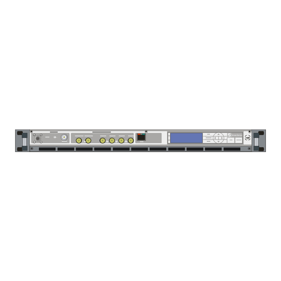
Screen Service SDT 200UB – SDT 500UB ARK-1 ATSC Operations 3.1.5 FRONT PANEL ARK 1 Front Panel Label Description RF INPUT GPS IN ASI OUTPUT HP ASI OUTPUT LP DIGITAL in 1 DIGITAL in 2 DIGITAL in 3 DIGITAL in 4... -
Page 29: Fig. 1: Aux Remote Connector
Screen Service SDT 200UB – SDT 500UB ARK-1 ATSC Operations AUX REMOTE CONNECTOR Sub-D 25 Male. ASSIGNMENT REMARKS Not used Alarm reset in opto active to gnd Remote STBY in opto active to gnd GND OPTO SERIAL 485/232 SERIAL 485/232... -
Page 30: Multimeter
Screen Service SDT 200UB – SDT 500UB ARK-1 ATSC Operations 3.2 MULTIMETER The following paragraphs describe the local user interface for ARK1. This user interface is composed of LCD Display, seven buttons and two status leds. Here below is depicted the ARK1 Front Panel. -
Page 31: Local Interrface Menu Tree
Screen Service SDT 200UB – SDT 500UB ARK-1 ATSC Operations 3.2.1 LOCAL INTERRFACE MENU TREE Main display LEGEND menu Menu Network setup Multiple choice IP addr GBE Data R A1:A2:A3:A4 Data W Gateway GBE G1:G2:G3:G4 Netmask GBE N1:N2:N3:N4 System Status... - Page 32 Screen Service SDT 200UB – SDT 500UB ARK-1 ATSC Operations Main display LEGEND menu Menu System status Multiple choice Tuner Data R Input channel Data W Input offset Input squelch Rx level Output Output RF status Frequency ref Channel Offset...
-
Page 33: Fig. 2: Local Interface Menu Tree
Screen Service SDT 200UB – SDT 500UB ARK-1 ATSC Operations Main display LEGEND menu Menu Multiple choice Reset system Data R Data W Change mode Mode A Mode B Time and Date Time Date Fig. 2: Local Interface Menu Tree July, 2009 v 1.0... -
Page 34: Boot And Welcome Message
Screen Service SDT 200UB – SDT 500UB ARK-1 ATSC Operations 3.2.2 BOOT AND WELCOME MESSAGE Turning on the equipment, the display shows the progress bar as follow: Screen Service Screen Service ARK - ATSC/ITU.470 ARK - ATSC/ITU.470 System Init Boot FPGA... -
Page 35: Main Menu
Screen Service SDT 200UB – SDT 500UB ARK-1 ATSC Operations Table 1. Local User Interface: Idle Menu Information Description • ARK - ATSC: ATSC modulator Operating mode • ARK - ITU 470: NTSC modulator • Input In: input selected •... -
Page 36: Lcd Alarms
Screen Service SDT 200UB – SDT 500UB ARK-1 ATSC Operations Reset system Enter this submenu to reset the device. Enter this submenu to change operating Change mode mode (A or B). Enter this submenu to change Time and Time and Date Date 3.2.5 LCD alarms... - Page 37 Screen Service SDT 200UB – SDT 500UB ARK-1 ATSC Operations Alarm Alarm Message Bad File in File system File error No TS Input In. not detected FPGA Boot alarm FPGA boot err Warm up alarm Sys. warm up July, 2009 v 1.0...
-
Page 38: Snmp - Simple Network Management Protocol
Screen Service SDT 200UB – SDT 500UB ARK-1 ATSC Operations 3.3 SNMP – SIMPLE NETWORK MANAGEMENT PROTOCOL The SNMP model assumes the existence of managers and agents. A manager is a software module in a management system responsible for managing the device. An agent is a software module in a managed device responsible for maintaining local management information and delivering that information to a manager via SNMP. -
Page 39: Monitoring
Screen Service SDT 200UB – SDT 500UB ARK-1 ATSC Operations Next figure illustrates how to configure SNMP Protocol Preferences using MG_SOFT MIB Browser as an example. Fig. 3: SNMP Protocol Preferences 3.3.2 Monitoring All status and setup information can be queried via SNMP. To get the setup and status information you need a management system (or a special MIB browser). -
Page 40: Oid
Screen Service SDT 200UB – SDT 500UB ARK-1 ATSC Operations 3.3.3 OID Any status and setup information has an OID (Object Identifier). The OID of the ARK1 ATSC system is: • screenservice_ark1atsc: 1.3.6.1.4.1.21678.186 iso(1).org(3).odd(6).internet(1).private(4).enterprises(1).screenservice(21678).scree nservice_ark1atsc(186) 3.3.4 SNMP tree structure The screenservice_ark1atsc tree has 12 nodes and 1 leave. - Page 41 Screen Service SDT 200UB – SDT 500UB ARK-1 ATSC Operations Name Description 1.3.6.1.2.1.1.4 sysContact 1.3.6.1.2.1.1.5 sysName 1.3.6.1.2.1.1.6 sysLocation 1.3.6.1.2.1.1.7 sysServices 1.3.6.1.4 private 1.3.6.1.4.1 enterprise 1.3.6.1.4.1.21678 screenservice 1.3.6.1.4.1.21678.186 screenservice_ark1atsc 1.3.6.1.4.1.21678.186.1 ark1atsc_SystemInfo 1.3.6.1.4.1.21678.186.1.1 ark1atsc_SystemInfoIdentifier Identification name of the equipment managed 1.3.6.1.4.1.21678.186.1.2 ark1atsc_SystemInfoName Manufacturer name 1.3.6.1.4.1.21678.186.1.3...
- Page 42 Screen Service SDT 200UB – SDT 500UB ARK-1 ATSC Operations Name Description 1.3.6.1.4.1.21678.186.2.7 ark1atsc_ModeActualTmo Actual auto-switch timeout (s) Auto-switch rules mode A (bit to alarm 1.3.6.1.4.1.21678.186.2.8 ark1atsc_ModeAutoSwitchRuleA association) 0: no rules 4: no TS input rule Auto-switch rules mode B (bit to alarm 1.3.6.1.4.1.21678.186.2.9...
- Page 43 Screen Service SDT 200UB – SDT 500UB ARK-1 ATSC Operations Name Description Mode B: Itu 470 audio channel selector 0: CH 1.3.6.1.4.1.21678.186.3.1.2.3.2 ark1atsc_SettingsB_Itu_Audio_Ch 1,2 1: CH 3,4 1.3.6.1.4.1.21678.186.3.2 ark1atsc_InputStatistics 1.3.6.1.4.1.21678.186.3.2.1 ark1atsc_StatisticsRf Input RX level 0: over input 255: low power 1...254: power (absolute value expressed in...
- Page 44 Screen Service SDT 200UB – SDT 500UB ARK-1 ATSC Operations Name Description 1.3.6.1.4.1.21678.186.3.2.2.1.2 ark1atsc_AsiSsi2Lock Asi 2 lock status 0: unlock 1: lock 1.3.6.1.4.1.21678.186.3.2.2.1.2 ark1atsc_AsiSsi2PacketFormat Asi 2 packet format 0: 204 1: 188 1.3.6.1.4.1.21678.186.3.2.2.1.2 ark1atsc_AsiSsi2Cd Asi 2 carrier detect alarm 0: unlock 1: lock 1.3.6.1.4.1.21678.186.3.2.2.1.2...
- Page 45 Screen Service SDT 200UB – SDT 500UB ARK-1 ATSC Operations Name Description 1.3.6.1.4.1.21678.186.3.2.2.1.4 ark1atsc_AsiSsi4PacketFormat Asi 4 packet format 0: 204 1: 188 1.3.6.1.4.1.21678.186.3.2.2.1.4 ark1atsc_AsiSsi4Cd Asi 4 carrier detect alarm 0: unlock 1: lock 1.3.6.1.4.1.21678.186.3.2.2.1.4 Asi 4 wrong bytes received (pay attention: when...
- Page 46 Screen Service SDT 200UB – SDT 500UB ARK-1 ATSC Operations Name Description error 0: off 1: on 1.3.6.1.4.1.21678.186.3.2.2.2.4 Not implemented - GbE Rx channel 2 ark1atsc_GbeRxCh2Protocol transmission protocol 0: udp 1: rtp 1.3.6.1.4.1.21678.186.3.2.3 ark1atsc_StatisticsItu 1.3.6.1.4.1.21678.186.3.2.3.1 ark1atsc_ItuSdi 1.3.6.1.4.1.21678.186.3.2.3.1.1 ark1atsc_Sdi1 1.3.6.1.4.1.21678.186.3.2.3.1.1 ark1atsc_Sdi1Lock Sdi 1 lock status 0: unlock 1: lock 1.3.6.1.4.1.21678.186.3.2.3.1.1...
- Page 47 Screen Service SDT 200UB – SDT 500UB ARK-1 ATSC Operations Name Description evel range 0 to 140) 1.3.6.1.4.1.21678.186.4.1.2.2 ark1atsc_Modulation_Itu_Audio ark1atsc_Modulation_Itu_Audio_Deviatio 1.3.6.1.4.1.21678.186.4.1.2.2.1 Audio deviation ark1atsc_Modulation_Itu_Audio_CarrierL Carrier Level 1 [dB] (range: -7 to -22) = [-1* 1.3.6.1.4.1.21678.186.4.1.2.2.2 evel1 (x/10)] (range 70 to 220)
- Page 48 Screen Service SDT 200UB – SDT 500UB ARK-1 ATSC Operations Name Description 1.3.6.1.4.1.21678.186.5.1.2.3 ark1atsc_SettingsBPower Mode B: output power 1.3.6.1.4.1.21678.186.5.1.3 ark1atsc_OutputSettingsGbe 1.3.6.1.4.1.21678.186.5.1.3.1 ark1atsc_SettingsGbeTxCh1 Not implemented - Input to GbE Tx Ch 1 selector 0: asi 1 1: asi 2 2: asi 3 3: asi 4 4: ssi 1 5: ssi 2 6: ssi 3 7: ssi 4 8: Gbe Ch1 9: Gbe 1.3.6.1.4.1.21678.186.5.1.3.1.1 ark1atsc_GbeTxCh1Selector...
- Page 49 Screen Service SDT 200UB – SDT 500UB ARK-1 ATSC Operations Name Description 1.3.6.1.4.1.21678.186.5.4.2 ark1atsc_NotUsed 1.3.6.1.4.1.21678.186.5.5 ark1atsc_OutputMonitor 1.3.6.1.4.1.21678.186.5.5.1 ark1atsc_Monitor_FwdPowerDbm Forward power [dBm x 10] indicator 1.3.6.1.4.1.21678.186.5.5.2 ark1atsc_Monitor_AgcMode AGC mode status 0: analog 1: digital 1.3.6.1.4.1.21678.186.5.5.3 ark1atsc_Monitor_AgcOn Auto AGC status 0: off 1: on 1.3.6.1.4.1.21678.186.6...
- Page 50 Screen Service SDT 200UB – SDT 500UB ARK-1 ATSC Operations Name Description 1.3.6.1.4.1.21678.186.7 ark1atsc_Gps 1.3.6.1.4.1.21678.186.7.1 ark1atsc_GpsSat 1.3.6.1.4.1.21678.186.7.1.1 ark1atsc_SatVisible Number of visible satellite 1.3.6.1.4.1.21678.186.7.1.2 ark1atsc_SatTracked Number of satellite locked 1.3.6.1.4.1.21678.186.7.2 ark1atsc_GpsStatus 1.3.6.1.4.1.21678.186.7.2.1 ark1atsc_StatusDataValid Signal precision status 0: Not valid 1: Valid 1.3.6.1.4.1.21678.186.7.3...
- Page 51 Screen Service SDT 200UB – SDT 500UB ARK-1 ATSC Operations Name Description address 1.3.6.1.4.1.21678.186.9.3.5 ark1atsc_TxChannel1Port Not implemented - Tx channel 1: destination port 1.3.6.1.4.1.21678.186.9.3.6 ark1atsc_TxChannel1Ssrc Not implemented - Tx channel 1: SSRC identifier Not implemented - Tx channel 1: destination 1.3.6.1.4.1.21678.186.9.3.7...
- Page 52 Screen Service SDT 200UB – SDT 500UB ARK-1 ATSC Operations Name Description 1.3.6.1.4.1.21678.186.9.7.6 ark1atsc_Trap5IpAddress Trap 5: destination IP address 1.3.6.1.4.1.21678.186.9.7.7 ark1atsc_Trap6IpAddress Trap 6: destination IP address 1.3.6.1.4.1.21678.186.9.7.8 ark1atsc_Trap7IpAddress Trap 7: destination IP address 1.3.6.1.4.1.21678.186.10 ark1atsc_Alarm 1.3.6.1.4.1.21678.186.10.1 ark1atsc_AlarmThr 1.3.6.1.4.1.21678.186.10.1.1 ark1atsc_Not_implemented 1.3.6.1.4.1.21678.186.10.1.2...
- Page 53 Screen Service SDT 200UB – SDT 500UB ARK-1 ATSC Operations Name Description 1.3.6.1.4.1.21678.186.10.6 ark1atsc_AlarmJavaEnable Java: alarm mask 1.3.6.1.4.1.21678.186.10.7 ark1atsc_AlarmEventEnable Events: alarm mask 1.3.6.1.4.1.21678.186.10.8 ark1atsc_AlarmRfOffEnable RF Off: alarm mask 1.3.6.1.4.1.21678.186.10.9 ark1atsc_AlarmSingleStatus 1.3.6.1.4.1.21678.186.10.9.1 ark1atsc_UpconvUnlockStatus Upconverter Oscillator Unlock alarm status 1.3.6.1.4.1.21678.186.10.9.2 ark1atsc_PsVoltageStatus PS Voltage out of range alarm status 1.3.6.1.4.1.21678.186.10.9.3...
-
Page 54: Configuring Alarms Masks
Screen Service SDT 200UB – SDT 500UB ARK-1 ATSC Operations Name Description 1.3.6.1.4.1.21678.186.10.9.32 ark1atsc_WarmUpStatus Warm up alarm status 1.3.6.1.4.1.21678.186.11 ark1atsc_Config 1.3.6.1.4.1.21678.186.11.1 ark1atsc_ConfigLoad Load configuration 1.3.6.1.4.1.21678.186.11.2 ark1atsc_ConfigSave Save configuration 1.3.6.1.4.1.21678.186.11.3 ark1atsc_ConfigReset Reset board LCD stand-by button enable 0: disabled 1: 1.3.6.1.4.1.21678.186.11.4... -
Page 55: Fig. 5:Configuring Alarms
Screen Service SDT 200UB – SDT 500UB ARK-1 ATSC Operations Fig. 5:Configuring alarms There are six families of alarm masks: • ark1atsc_AlarmJavaEnable: the selected alarms status is notified on the Java alarm page icon. • ark1atsc_AlarmFrontPanelEnable: the selected alarms status is notified on LCD display lighting the alarm button and listing the alarms in the Alarms menu (refer to Alarms Menu paragraph). -
Page 56: Traps
Screen Service SDT 200UB – SDT 500UB ARK-1 ATSC Operations Bit-to-alarm association map Table 4. Alarm Alarm Up converter Osc. Unlock Signal 10 MHz Lock PS Voltage out range Signal 129 MHz Lock PS Current out of range Signal 960 MHz Lock Absolute Power Limiter Down Converter Osc. -
Page 57: Fig. 6:Configuring Traps
Screen Service SDT 200UB – SDT 500UB ARK-1 ATSC Operations The configuration of traps is performed through the setting of a trap alarm mask, by means of leaves housed in the ark1atsc_AlarmTrap node (refer to Configuring alarms paragraph), and through the setting of the destination IP Address of the receiving management stations, by means of leaves housed in the ark1atsc_Network node as shown in next figure. - Page 58 Screen Service SDT 200UB – SDT 500UB ARK-1 ATSC Operations Each trap carries a 32 bits word in which each alarm represents one bit (0: Off, 1: On). The following table shows the bit-to-alarm association. Bit-to-trap association map Table 5.
-
Page 59: Standalone/Driver Working Modes
Screen Service SDT 200UB – SDT 500UB ARK-1 ATSC Operations 3.4 STANDALONE/DRIVER WORKING MODES Two different working modes are provided: • Stand-alone: the device works in stand-alone mode. The system configuration can be totally set through user interfaces. Pre-correction curves are automatically selected according to channel and power range. - Page 60 Screen Service SDT 200UB – SDT 500UB ARK-1 ATSC Operations Table 6. Driver mode Issue Ethernet Java SNMP Ethernet Char interface Local OPTO Interface – interface Interface Port 10001 – Port (Display) 5000 Block output Commands: Java SNMP Commands: “W” or...
- Page 61 Screen Service SDT 200UB – SDT 500UB ARK-1 ATSC Operations Issue Ethernet Java SNMP Ethernet Char interface Local OPTO Interface – interface Interface Port 10001 – Port (Display) 5000 enabled. commands. Block mode Commands: Java SNMP Commands: “W” or Command...
-
Page 62: Transport-Level Protocols
Screen Service SDT 200UB – SDT 500UB ARK-1 ATSC Operations 3.5 TRANSPORT-LEVEL PROTOCOLS ARK 1 ATSC device allows connections over different ports and using different transport protocols over Gigabit Ethernet depending on functions and operations. In the following table used ports and protocols are listed to help users understand what software functions allow multiple connections and which port must be enabled. -
Page 63: Java(Tm) Platform
Screen Service SDT 200UB – SDT 500UB ARK-1 ATSC Operations 3.6 JAVA(TM) PLATFORM 3.6.1 Download The Java Interface works with any Sun Java Virtual Machine after the 1.4.1 version. If the computer has no Java Virtual Machine installed, the recommended 1.5.0 version can be downloaded from the Sun Server trough this link: http://www.java.com/. -
Page 64: Supported Web Browsers
Screen Service SDT 200UB – SDT 500UB ARK-1 ATSC Operations 2. The following window will suddenly appear. Fig. 9: Java Control Panel 3. Select “Settings…” in the “Temporary Internet Files” section of the “General” tab. 4. Deselect the check box of the “Keep temporary files on my computer” (disable cache). -
Page 65: Java Remote Graphic User Interface
Screen Service SDT 200UB – SDT 500UB ARK-1 ATSC Operations 3.7 JAVA REMOTE GRAPHIC USER INTERFACE The Java Graphic User Interface, stored in the board File System, is downloaded to the local PC every time the user connects to the board with a Web Browser. A proper Java Virtual Machine is needed;... -
Page 66: Fig. 13: Operation Pages Bar
Screen Service SDT 200UB – SDT 500UB ARK-1 ATSC Operations AM/PM pre-correction: allows management of AM/PM pre-correction curves tool. Output: allows to set output parameters, specific for each operative mode, and to monitor the hardware status (ITU 470 modulator and ATSC modulator). -
Page 67: General
Screen Service SDT 200UB – SDT 500UB ARK-1 ATSC Operations 3.7.2 General Click on General button icon, highlighted in the nex figure, to access the general window. Fig. 15: General window The General window provides a general description of the device and allows accessing a subset of commands through the following buttons: •... -
Page 68: Input
Screen Service SDT 200UB – SDT 500UB ARK-1 ATSC Operations 3.7.3 Input Click on Input button icon, highlighted in the nex figure, to access the input window. Fig. 16: Input window The Input window allows the monitoring of: • ASI/SSI and GbE input statistics for ATSC modulator;... - Page 69 Screen Service SDT 200UB – SDT 500UB ARK-1 ATSC Operations Table 8. Input window Parameter / Description Admitted Ranges / Values Control ASI/SSI Word rate ASI input word rate. 10 bits word rate of ASI input (Ref. to CEI EN 50083-9).
- Page 70 Screen Service SDT 200UB – SDT 500UB ARK-1 ATSC Operations Parameter / Description Admitted Ranges / Values Control ASI/SSI Word Errors Total amount of ASI wrong words received. • Protocol Not implemented - Ethernet input packets protocol. • Bitrate [bit/s] Not implemented - Bitrate of TS from Ethernet input.
- Page 71 Screen Service SDT 200UB – SDT 500UB ARK-1 ATSC Operations Parameter / Description Admitted Ranges / Values Control GBE packets Not implemented - Total amount of good Ethernet frames received. • 10 Mbit//s Speed Not implemented - Ethernet connection speed. No duplex information is provided.
- Page 72 Screen Service SDT 200UB – SDT 500UB ARK-1 ATSC Operations Parameter / Description Admitted Ranges / Values Control • 0: NTSC 4:2:2 component video; • 1: invalid; • 2: NTSC 4:2:2 16x9 component video; • 3: NTSC 4:4:4 13,5 MHz component Standard Standard of received SDI.
-
Page 73: Tuner
Screen Service SDT 200UB – SDT 500UB ARK-1 ATSC Operations 3.7.4 Tuner Click on Tuner button icon, highlighted in the nex figure, to access the tuner window. Fig. 17: Tuner window This window provides commands that allow the selection of working modes, the management and selection of inputs, and the monitoring of input RF signal level. - Page 74 Screen Service SDT 200UB – SDT 500UB ARK-1 ATSC Operations Table 9. Tuner window: modes management Parameter / Description Admitted Ranges / Values Control • System Mode & Mode A Actual mode Current operating mode. Autoswitching • Mode B System Mode &...
- Page 75 Screen Service SDT 200UB – SDT 500UB ARK-1 ATSC Operations Parameter / Description Admitted Ranges / Values Control System Mode & Switching Time Time and date setting for modes switching when Time Switch mode is enabled. Autoswitching Selector of working mode.
- Page 76 Screen Service SDT 200UB – SDT 500UB ARK-1 ATSC Operations Parameter / Description Admitted Ranges / Values Control • ASI 0 • ASI 1 • ASI 2 • ASI 3 • SSI 1 Mode A / Mode B Input ATSC Selector of ATSC TS input source.
- Page 77 Screen Service SDT 200UB – SDT 500UB ARK-1 ATSC Operations Parameter / Description Admitted Ranges / Values Control • CH 1,2 Mode A / Mode B Audio ITU470 Selector of ITU470 SDI audio channels. • CH 3,4 No RF, No TS...
-
Page 78: Modes Switching Rules
Screen Service SDT 200UB – SDT 500UB ARK-1 ATSC Operations 3.7.5 Modes switching rules Four switching rules are provided in order to cover different requirements: • Manual: switch between mode A and mode B by selecting one mode using the Manual Selector. - Page 79 Screen Service SDT 200UB – SDT 500UB ARK-1 ATSC Operations Table 11. Tuner window: Tuner management Parameter / Description Admitted Ranges / Values Control Turner Main Rx level RF input rx level monitoring. • Min: 0.000001 Turner Main BER Threshold Not implemented - Demodulator Bit Error Rate alarm threshold.
-
Page 80: Modulation
Screen Service SDT 200UB – SDT 500UB ARK-1 ATSC Operations 3.7.7 Modulation Click on Modulation button icon, highlighted in the nex figure, to access the modulation window. Fig. 18: Modulator window July, 2009 v 1.0 Page 3 - 58... - Page 81 Screen Service SDT 200UB – SDT 500UB ARK-1 ATSC Operations Table 12. Modulator window Parameter / Description Admitted Ranges / Values Control • Not checked: CW disabled Test: ATSC & ITU CW check box. • Checked: CW enabled • Not checked: Force Null packets...
- Page 82 Screen Service SDT 200UB – SDT 500UB ARK-1 ATSC Operations Parameter / Description Admitted Ranges / Values Control • MIN: 0 Tone Right Test: ITU 470 Right tone frequency setting. Not used for NTSC [100 KHz] • MAX: 127 •...
- Page 83 Screen Service SDT 200UB – SDT 500UB ARK-1 ATSC Operations Parameter / Description Admitted Ranges / Values Control • MIN: 10 Modulation ITU470 Video white level setting. The level value is in percentage upon the synch level. The synch level is White level [%] •...
- Page 84 Screen Service SDT 200UB – SDT 500UB ARK-1 ATSC Operations Parameter / Description Admitted Ranges / Values Control • MIN: -7 Modulation ITU470 Carrier Level 1 Audio 2 carrier level setting. • MAX: -22 audio [dB] • Step: 0,1 •...
- Page 85 Screen Service SDT 200UB – SDT 500UB ARK-1 ATSC Operations Parameter / Description Admitted Ranges / Values Control • mono dual carrier • dual sound Modulation ITU470 Audio Type Audio type selector. Only the mono single carrier audio type is used for NTSC.
-
Page 86: Filter
Screen Service SDT 200UB – SDT 500UB ARK-1 ATSC Operations 3.8 Filter The Adaptive Filter provides the ARK1 ATSC with an effective adaptive linear compensation. The adaptive filter works only in ATSC operative mode. The developed system is responsible for pre-emptively compensating an ATSC signal in order to make unimportant the contribution of the system transmission section. -
Page 87: Management Panel
Screen Service SDT 200UB – SDT 500UB ARK-1 ATSC Operations Click on Filter button icon, highlighted in the nex figure, to access the filter window. Fig. 20: Filter window This window provides commands and monitors for adaptive filter management and is organized in four subwindows: •... - Page 88 Screen Service SDT 200UB – SDT 500UB ARK-1 ATSC Operations 3.8.1 Management panel Table 13. Filter window: management panel Parameter / Description Admitted Ranges / Values Control Read To read and loads the filter coefficients from the respective FPGA registers..
- Page 89 Screen Service SDT 200UB – SDT 500UB ARK-1 ATSC Operations Ref Level To monitor the power control coefficient value applied for the transmission. Power Tx Signal Power To monitor the power value of the modulated signal at the input. Mean Square To monitor the Mean Square Error value of the compensate signal.
-
Page 90: Module Graph
Screen Service SDT 200UB – SDT 500UB ARK-1 ATSC Operations 3.8.2 Complex filter coefficients graph Fig. 21: Filter window: complex filter coefficients graph This graph shows the actual coefficients values applied. The circles indicate the coefficients real values, the red crosses indicate the imaginary ones. -
Page 91: Am/Pm Pre-Correction Tool
Screen Service SDT 200UB – SDT 500UB ARK-1 ATSC Operations 3.8.5 AM/PM pre-correction tool The ARK1 ATSC system provides a pre-correction tool for AM/PM output signal pre- correction. Remember to click on the Save as button the first time you change the factory default curves in order to do not overwrite them. - Page 92 Screen Service SDT 200UB – SDT 500UB ARK-1 ATSC Operations The tool is prevented to send an “overflowing” amount of data to the device: curve changes will be applied only when the mouse button is released. In the module grid, the red curve is used to monitor the current module curve calculating and saving.
-
Page 93: Connection To Port 5000
Screen Service SDT 200UB – SDT 500UB ARK-1 ATSC Operations 3.8.6 Connection to port 5000 The connection to port 5000 is performed every time the pre-correction tool is opened through AM/PM button, from Java interface. The pre-correction tool opens and keeps busy... -
Page 94: Output
Screen Service SDT 200UB – SDT 500UB ARK-1 ATSC Operations 3.8.7 Output Click on Output button icon, highlighted in the nex figure, to access the output window. Fig. 25: Output window Use the Output window to change and monitor both Ethernet and RF output settings, and all accessible hardware indicators. - Page 95 Screen Service SDT 200UB – SDT 500UB ARK-1 ATSC Operations Output window Table 15. Parameter / Description Admitted Ranges / Values Control Output RF signal enabling. The possible output RF signal status are the following: • Green: ON • ON / OFF •...
- Page 96 Screen Service SDT 200UB – SDT 500UB ARK-1 ATSC Operations Parameter / Description Admitted Ranges / Values Control • Green: ON AGC ON AGC status. • Grey: OFF • Analog/Digital: Mode Current AGC mode indicator. • Green: ON • Grey: OFF...
- Page 97 Screen Service SDT 200UB – SDT 500UB ARK-1 ATSC Operations Parameter / Description Admitted Ranges / Values Control • • • Restart • Stand-by off • GPS Off Status Ampli status Current amplifier status indicator. • Init • Alarm off •...
- Page 98 Screen Service SDT 200UB – SDT 500UB ARK-1 ATSC Operations Parameter / Description Admitted Ranges / Values Control PSU voltage indicator (values are expressed in V). It depends on the hardware type of the device: • Status 28V / 42V 28V for SDTx_ARK1 20W and 50W;...
- Page 99 Screen Service SDT 200UB – SDT 500UB ARK-1 ATSC Operations Parameter / Description Admitted Ranges / Values Control Reflex Power Status Output reflex power indicator (values are expressed in dBm). [dBm] • Alarm: indicator of an alarm condition • Mode: indicator of operating Opto &...
- Page 100 Screen Service SDT 200UB – SDT 500UB ARK-1 ATSC Operations Parameter / Description Admitted Ranges / Values Control Opto status indicators. Optos are normally opened: • Opto 0: RF Off, manual switching off of output RF; • Green: Closed (0) •...
- Page 101 Screen Service SDT 200UB – SDT 500UB ARK-1 ATSC Operations Parameter / Description Admitted Ranges / Values Control Mode A / Mode B Power [W] Output power (expressed in W). • Min: -4 MHz Mode A / Mode B Offset [Hz] Output frequency offset (expressed in Hz).
- Page 102 Screen Service SDT 200UB – SDT 500UB ARK-1 ATSC Operations Parameter / Description Admitted Ranges / Values Control FWD Power Alarm [dB] Forward power alarm threshold expressed in dBm. Thresholds Temperature Warning Case temperature warning threshold expressed in °C. •...
- Page 103 Screen Service SDT 200UB – SDT 500UB ARK-1 ATSC Operations Parameter / Description Admitted Ranges / Values Control • ASI 0 • ASI 1 • ASI 2 • ASI 3 • SSI 1 Output GbE Ch.1 Input Source selector for transmission on GbE channel 1/2. Not implemented / Ch.
- Page 104 Screen Service SDT 200UB – SDT 500UB ARK-1 ATSC Operations Parameter / Description Admitted Ranges / Values Control • Resolving IP Addr. • IP not found • No entry Output GbE Ch.1 Status Status indicator of transmission on GbE channel 1/2. Not implemented •...
-
Page 105: Network
Screen Service SDT 200UB – SDT 500UB ARK-1 ATSC Operations 3.8.8 Network Click on Network button icon, highlighted in the nex figure, to access the Network management window. Fig. 26: Network window This window allows the Network parameters management and monitoring. - Page 106 Screen Service SDT 200UB – SDT 500UB ARK-1 ATSC Operations Table 16. Network window Parameter / Description Admitted Ranges / Values Control Board IP Local Board IP address. address Board MAC Local Board MAC address. address Local Gateway Gateway address.
- Page 107 Screen Service SDT 200UB – SDT 500UB ARK-1 ATSC Operations Parameter / Description Admitted Ranges / Values Control • Min: 0 Input GbE Ch.1/ Port Channel 1/2 receiving port. Not implemented. Ch.2 • Max: 65,535 • UDP/RTP: Input GbE Ch.1/ Protocol Ethernet input packets protocol.
- Page 108 Screen Service SDT 200UB – SDT 500UB ARK-1 ATSC Operations Parameter / Description Admitted Ranges / Values Control • 188 Bytes Input GbE Ch.1/ Format Received transmission format. Not implemented. Ch.2 • 240 Bytes • Green: Lock Input GbE Ch.1/ Ethernet input lock status indicator.
- Page 109 Screen Service SDT 200UB – SDT 500UB ARK-1 ATSC Operations Parameter / Description Admitted Ranges / Values Control • 10 Mbit//s Gbe statistic Speed Ethernet speed. • 100 Mbit//s • 1 Gbit/s Gbe statistic GBE Errors Total amount of bad frames received.
- Page 110 Screen Service SDT 200UB – SDT 500UB ARK-1 ATSC Operations Parameter / Description Admitted Ranges / Values Control • Resolving IP Addr. • IP not found • No entry Output GbE Ch.1 Status Ethernet transmission on channel 1/2 status indicator. Not implemented.
- Page 111 Screen Service SDT 200UB – SDT 500UB ARK-1 ATSC Operations Parameter / Description Admitted Ranges / Values Control • Output GbE Ch.1 Frame type Transmission protocol selector. Not implemented. / Ch.2 • • 188 Bytes Output GbE Ch.1 TS Format Transmission format.
-
Page 112: Gps
Screen Service SDT 200UB – SDT 500UB ARK-1 ATSC Operations 3.8.9 GPS Click on GPS button icon, highlighted in the nex figure, to access the GPS received statistics window. Fig. 27: GPS window July, 2009 v 1.0 Page 3 - 90... - Page 113 Screen Service SDT 200UB – SDT 500UB ARK-1 ATSC Operations GPS window Table 17. Parameter / Description Admitted Ranges / Values Control #Number of Satellite Number of visible GPS satellites indicator. Visible sat #Number of Satellite Number of tracked GPS satellites indicator.
-
Page 114: Alarms
Screen Service SDT 200UB – SDT 500UB ARK-1 ATSC Operations 3.8.10 Alarms Click on Alarms button icon, highlighted in the nex figure, to access the alarms management window. Fig. 28: Alarms window The Alarm window allows the setting of alarm masks and the monitoring of alarms status. - Page 115 Screen Service SDT 200UB – SDT 500UB ARK-1 ATSC Operations In the Alarms window, when an alarm condition occurs, the relative alarm is red highlighted. The Total check box enables all alarms-to-masks associations. July, 2009 v 1.0 Page 3 - 93...
- Page 116 Screen Service SDT 200UB – SDT 500UB ARK-1 ATSC Operations Table 18. Alarms window Alarm Description Troubleshooting mask PLL of the Up-converter board not locked to 129 MHz Up converter Osc. Unlock • Hardware fault clock. Voltage out of range. The ranges are: •...
- Page 117 Screen Service SDT 200UB – SDT 500UB ARK-1 ATSC Operations Temperature High Warning Temperature level goes over the warning threshold. • Verify that the No RF Input alarm is enabled in the RF Off alarms mask Forward Power High FWD power goes over the maximum endurable limit.
- Page 118 Screen Service SDT 200UB – SDT 500UB ARK-1 ATSC Operations • Check fans connections One of the fans speeds is under the minimum speed level Fan Speed • Verify that fans are not damaged; in this case substitute them. (1,000 rpm).
- Page 119 Screen Service SDT 200UB – SDT 500UB ARK-1 ATSC Operations • If the Network’s Transmitters Synchronization is SFN, check the frequency reference: it should be other than internal • If the frequency reference is Internal: internal PLL fault • If the frequency reference is External: Internal PLL fault •...
- Page 120 Screen Service SDT 200UB – SDT 500UB ARK-1 ATSC Operations • GPS communication error alarm is not signaled • • GPS lock alarm is not signaled 129 MHz oscillator can loose the lock Signal 129 MHz Lock • • 10 MHz lock alarm is not signaled Hardware fault •...
- Page 121 Screen Service SDT 200UB – SDT 500UB ARK-1 ATSC Operations Not implemented File System Error File System loading error. • File system partition damage July, 2009 v 1.0 Page 3 - 99...
- Page 122 Screen Service SDT 200UB – SDT 500UB ARK-1 ATSC Operations One more of the following files missing in the File System. • *.def; • *.sav; • *.apwr; • *.dpwr; • *.apre; • Check files list Bad File in File system •...
- Page 123 Screen Service SDT 200UB – SDT 500UB ARK-1 ATSC Operations • Device in ATSC mode • Selected TS input not locked. No TS Input X (1) • Check input statistics The No TS Input is an alarm of the Tx ATSC mode. It should be always enabled in the RF Off alarms mask while working in ATSC mode.
-
Page 124: Events
Screen Service SDT 200UB – SDT 500UB ARK-1 ATSC Operations 3.8.11 Events Click on Events button icon, highlighted in the nex figure, to access the events windos. Fig. 29: Events window This window allows to monitor the events list and to set the device time and date. -
Page 125: Events Monitoring
Screen Service SDT 200UB – SDT 500UB ARK-1 ATSC Operations Double click on the Time/Date field to change. Fig. 31: Time/Date field selected Click on the lateral up-arrows or on the down-arrows to respectively increase or decrease the value of the field selected. - Page 126 Screen Service SDT 200UB – SDT 500UB ARK-1 ATSC Operations Events descriptions list Table 19. Event Description Description RF OFF enabled from OPTO RF output switched off through OPTO 0. RF OFF disabled from OPTO RF output switched on through OPTO 0.
- Page 127 Screen Service SDT 200UB – SDT 500UB ARK-1 ATSC Operations Event Description Description This event is reported when one of the following alarms is risen: • Up converter Osc. Unlock • PS 28V out range • PS Current out of range PS Restart N •...
- Page 128 Screen Service SDT 200UB – SDT 500UB ARK-1 ATSC Operations Alarms descriptions list Table 20. Alarm Alarm Description Up converter Osc. Unlock UPCV Osc. not locked PS Voltage out of range PS voltage error PS Current out of range PS current error...
-
Page 129: Task Error Event
Screen Service SDT 200UB – SDT 500UB ARK-1 ATSC Operations 3.8.13 Task Error Event The watchdog performs a periodic (every 20 seconds) polling of tasks and triggers a system reset if more tasks answer, restarting Codeloader (See Codeloader_Operations_Note_v1.1.doc for further information) and generating a TSK ERR event as... -
Page 130: System Error Event
Screen Service SDT 200UB – SDT 500UB ARK-1 ATSC Operations 3.8.14 System Error Event For critical and fatal errors, the system calls the system error function and the SYS_ERR event is reported. The error code is describer below: • 0x00: Out of memory. Memory pool size is too small. -
Page 131: System Initialization Event
Screen Service SDT 200UB – SDT 500UB ARK-1 ATSC Operations 3.8.15 System Initialization Event At every system initialization the event System Init is generated. This event is followed by 25 bytes specifying type and specific code of errors occurred during system initialization. - Page 132 Screen Service SDT 200UB – SDT 500UB ARK-1 ATSC Operations Byte Description Errors code • 0x00: FPGA boot ok. • 0x01: FPGA configuration erasing process error. • 0x02: Invalid configuration (the BOOT_ERR 6° configuration has been correctly loaded, FPGA boot error.
- Page 133 Screen Service SDT 200UB – SDT 500UB ARK-1 ATSC Operations Byte Description Errors code • 0x00: File ok. • 0x01: Analog (Digital) mode (current mode) file not found. • 0x02: Analog (Digital) file open error. CALIB_ERR • 0x03…0x12: Invalid Analog (Digital) file 9°...
- Page 134 Screen Service SDT 200UB – SDT 500UB ARK-1 ATSC Operations Byte Description Errors code • 0x00: PLL locked. DOWNCV_ERR 12° Downconverter PLL not • 0x01: PLL not locked locked error. • 0x10: PLL disabled. • 0x00: Upconverter ready. UPCV_ERR •...
-
Page 135: System Menu
Screen Service SDT 200UB – SDT 500UB ARK-1 ATSC Operations 3.8.16 System menu Fig. 33: Menu bar The menu bar allows the access to three menus: • File: allows the enabling of load and save commands • View: allows to manage sections windows showing, java update time and events alert massages •... -
Page 136: View Menu
Screen Service SDT 200UB – SDT 500UB ARK-1 ATSC Operations 3.8.18 View menu Fig. 35: View menu The View menu allows the enabling of the following commands: • General: allows accessing the general window. • Input: allows accessing the input window. -
Page 137: Option Sub-Menu
Screen Service SDT 200UB – SDT 500UB ARK-1 ATSC Operations 3.8.18.1.1 Option sub-menu The Option sub-menu allows two controls type: • Time: Time Read Interval [s]; • Alerts: the selection of events to display. Click on the Save button to save Java options; a *.properties file will be created. -
Page 138: Fig. 38: Alert Message
Screen Service SDT 200UB – SDT 500UB ARK-1 ATSC Operations • Commands (blue boxes): Gigabit Ethernet commands; RS232 commands; SNMP commands; LCD Display commands. • Alarms (red boxes); • Events (green messages): Board events. • Typing error (yellow messages): Typed setting is incorrect. -
Page 139: Help Menu
Screen Service SDT 200UB – SDT 500UB ARK-1 ATSC Operations 3.8.19 Help menu Fig. 39: Help menu The Help menu allows enabling the following controls type: • Contents: actually not implemented. • About: shows the board name and the GbE IP address. It also informs about the board uC, fpga and java software versions. -
Page 140: Info
Screen Service SDT 200UB – SDT 500UB ARK-1 ATSC Operations 3.8.19.2 Info Fig. 41: Info window: file system content The server file system content section of info window shows the entire board system files list. Use scroll bars to view all the items. -
Page 141: Fig. 43: Download Software Standalone
Screen Service SDT 200UB – SDT 500UB ARK-1 ATSC Operations • Click on the Tools button and then click on Internet Options; • Click on the Security tab and then click on Custom level button; • To turn off the Information bar for file downloads, scroll to the Downloads section of the list, and then, under Automatic prompting for file downloads, click on Enable;... - Page 142 Screen Service SDT 200UB – SDT 500UB ARK-1 ATSC Technical Information SDT 200UB – SDT 500UB ARK-1 ATSC Software Defined Transmitter OPERATION MANUAL 4 TECHNICAL INFORMATION CONTENTS FIGURE AND TABLES LIST July, 2009 v 1.0 Page 4 - 1...
- Page 143 Screen Service SDT 200UB – SDT 500UB ARK-1 ATSC Technical Information This chapter is left intentionally blank. July, 2009 v 1.0 Page 4 - 2...
- Page 144 Screen Service SDT 200UB – SDT 500UB ARK-1 ATSC Manual change information SDT 500UB ARK 1 Software DefinedTransmitter OPERATION MANUAL 5 MANUAL CHANGE INFORMATION CONTENTS INTRODUCTION.............................5 - 2 July, 2009 v 1.0 Page 5 - 1...
- Page 145 Screen Service SDT 200UB – SDT 500UB ARK-1 ATSC Manual change information 5.1 INTRODUCTION At Screen Service, we continually try to keep our customers up with the latest technology by adding circuit and component improvements to our equipment as soon as they are developed and tested.
Need help?
Do you have a question about the SDT 500UB ARK-1 ATSC and is the answer not in the manual?
Questions and answers