
Summary of Contents for MFZ CS 300
- Page 1 Operating Instructions for Control CS 300 2006 CS 300 Gate Controls / rev. 04.06 - 1...
-
Page 3: Table Of Contents
Initial Operation Programming with the LED module MFZ Antriebe GmbH + Co.KG is not liable for any Programming with the LCD monitor personal injury or damage to property that occurs as Navigator (LCD monitor only) -
Page 4: Overview Of Products
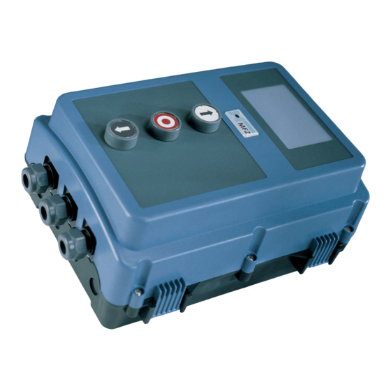
CS 300 controls: - CS 300 control with LCD monitor Construction product standards - CS 300 control with LCD monitor in housing - EN 13241-1 (Products without fi re resistance or - CS 300 control with LED module for setting... - Page 5 X10: sockets for weekly timer X11: sockets for digital end-position system X12: socket for external radio receiver status display for safety edge protection (SEP) – illuminated when SEP is working 4 – CS 300 Gate Controls / rev. 04.06...
-
Page 6: Initial Operation
fi eld is required. ☞ - For a permanent connection, an all-pole main switch must be used. - For a three-phase connection, only 3-way automatic circuit breakers (10A) may be used. CS 300 Gate Controls / rev. 04.06 – 5... - Page 7 - relay 2 effective in down direction for external switching devices - relay 3 (connection to terminals 1 and 2) - relay 4 white green brown 6 – CS 300 Gate Controls / rev. 04.06...
- Page 8 Connect the command and safety devices to the ☞ control. control. OPEN / STOP / CLOSE buttons (4-lead solution) - CLOSE button - OPEN button - STOP button Key switch OPEN / CLOSE - CLOSE - OPEN CS 300 Gate Controls / rev. 04.06 – 7...
-
Page 9: Programming With The Led Module
The door is closed. The programmed CLOSED end position has been reached. The door is between end positions. No end position has been reached. The door has been moved beyond the CLOSED/OPEN end position. 8 – CS 300 Gate Controls / rev. 04.06... - Page 10 Drive the door into the desired CLOSED end position by pressing the - button. Drive the door into the desired CLOSED end position by pressing the - button. ☞ Save the end position by pressing simultaneously the P button and the - button. ☞ CS 300 Gate Controls / rev. 04.06 - 9...
-
Page 11: Programming With The Lcd Monitor
7.1 Overview of the LCD monitor Key: mode of operation / diagnostic info AUTOMATIC parameter / RESTING diagnostic info + button - button P button value / status value / status jumper 10 – CS 300 Gate Controls / rev. 04.06... - Page 12 The door can be damaged if driven beyond the end position. Fine adjustments can be made in the INPUT operating mode. Display: - displays the end position value CS 300 Gate Controls / rev. 04.06 – 11...
-
Page 13: Navigator (Lcd Monitor Only)
Navigator (LCD monitor only) 12 – CS 300 Gate Controls / rev. 04.06... - Page 14 CS 300 Gate Controls / rev. 04.06 - 13...
-
Page 15: Overview Of Functions
The door stands at the position PART CLOSE („before-end position“ down) RESTING AUTOMATIC The door stands in the position where the reversing switches off RESTING *When the gate is being driven OPEN, the power currently being used is displayed 14 – CS 300 Gate Controls / rev. 04.06... - Page 16 MOD3: Brake negated MOD3 MOD4: Brake remains ON during open time MOD4 MOD5: Brake remains ON during open time and direction turnaround MOD5 (relay switches OFF when turnaround initiated by SEP) CS 300 Gate Controls / rev. 04.06 - 15...
- Page 17 PART-OPEN button at terminal X4 (9 + 10) MOD1 MOD1 MOD2: PART-OPEN selector switch at terminal X4 (9 + 10) MOD2 When the selector switch is closed, all OPEN commands go to the before-end switch OPEN 16 – CS 300 Gate Controls / rev. 04.06...
- Page 18 STOP CIRCUIT - Stop button of controls circuit closed - Stop systems of drive OFF: interrupted (fault) CYCLE Gate-cycle counter Displays the gate cycles Absolute value encoder Shows the gate position value CS 300 Gate Controls / rev. 04.06 - 17...
-
Page 19: Error Messages And Rectifi Cation
- Check that the door can move freely triggered - Reset the power value After rectifying the cause of the fault, the controls must be disconnected briefl y from the mains! 18 – CS 300 Gate Controls / rev. 04.06... -
Page 20: Technical Data
EN 60335-2-103 BGR 232 - Directive for Power-driven Windows, Doors and Gates Directive for Power-driven Windows, Doors and Gates Legden, 1 February 2006 Manufacturer‘s signature: Hans-Joachim Molterer Position of signatory: Manager CS 300 Gate Controls / rev. 04.06 – 19...
Need help?
Do you have a question about the CS 300 and is the answer not in the manual?
Questions and answers