Advertisement
Advertisement
Table of Contents

Related Manuals for Wavecom DT-8852

Summary of Contents for Wavecom DT-8852
- Page 1 SOUND LEVEL METER INSTRUCTION MANUAL FAST...
-
Page 2: Safety Information
SAFETY INFORMATION Read the following safety information carefully before attempting to operate or service the meter. Use the meter only as specified in this manual: Environment conditions ① Altitude lower than 2000 meters ② Relatively humidity ≤90%RH ③ Operation Ambient 0 ~ 40℃ Maintenance &... -
Page 3: Specification
measurement. applied sounds measurement at factory; school; office; traffic access and household, etc. This unit confirms to the IEC61672-1 CLASS2 for Sound Level Meters. MAX & MIN measurements Over range display Under range display A & C Weighting FAST & SLOW response Analog AC/DC outputs for connection to frequency analyzer or X-Y shaft recorder 3. -
Page 4: Auto Power Off
Frequency weighting: Time weighting: FAST ( 125ms ), SLOW ( 1s ) Microphone: 1/2 inch electret condenser microphone Display: 4 digits LCD display with a resolution of 0.1dB Display Update: 2 times/sec. MAX hold: Hold the Maximum reading MIN hold: Hold the Minimum reading HOLD: Hold the readings... -
Page 5: Name And Functions
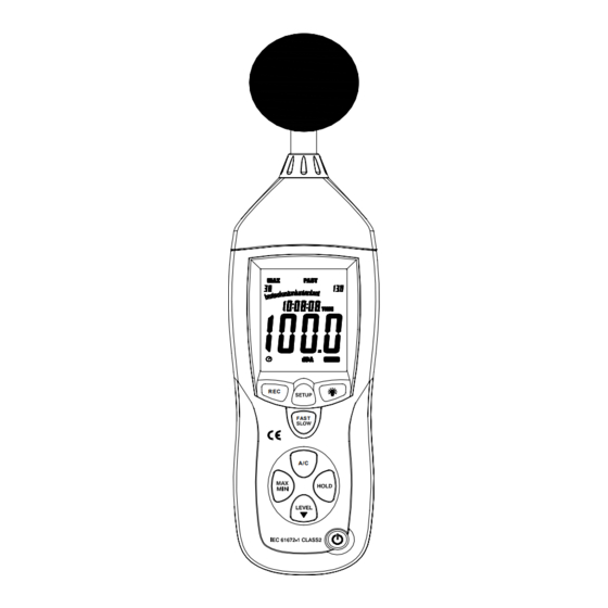
Power supply : One 9V battery, 006P or NEDA1604 or IEC 6F22. Power life : About 30hours Operation temperature and humidity: 0℃~40℃,10%RH~90%RH Storage temperature and temperature: -10℃~+60℃,10%RH~75%RH Dimension : 278 (L) x 76 (W) x 50(H) mm Weight : 350g Accessories : Instruction manual, battery, screwdriver,... - Page 6 ① Windscreen ② LCD:...
- Page 7 SYMBOL FUNCTION 4 digits Maximum hold Minimum hold OVER over range UNDER under range FAST Fast response SLOW Slow response A-Weighting(responseto human sense) C-Weighting(response machine monitor) 30—130 Range indicate Recording data into computer AUTO Auto level range selection FULL Memory full HOLD Data hold function AutopoweroffPress...
-
Page 8: Rec Button
③REC button 3.0 DATALOGGER function Press “REC” button after it power on, the display will show “REC” to start Data Recording,press the button again to exit the record (Note: In order to avoid data error, please don’t power it off under REC condition, when the REC function is deleted then it can power off). - Page 9 3.2 Data zero function Press the button continuously before power it on, loosen the button when the display showing‘CLR’ after the meter power on , which indicates that the data in DATALOGGER has been deleted. ④SETUP button 4.0.The time chip adjustment Press ‘SETUP’...
- Page 10 Press the ‘SETUP’ button second time, the display showing: The display showing “minute” adjustment mode, press ‘LEVEL’ to make the adjustment, press ‘HOLD’ keep the setup; Press the‘SETUP’button third time, the display showing: The display showing “hour” adjustment mode, press h-P=P.M h-A=A.M (...
- Page 11 The display showing “date” adjustment mode, press ‘ LEVEL ’ to make the adjustment , press keep the setup; ‘HOLD’to Press the‘SETUP’button fifth time, the display showing: The display showing “month” adjustment mode, press ‘LEVEL’ to make the adjustment, press ‘HOLD’ keep the setup;...
- Page 12 ‘LEVEL’ to make the adjustment, press ‘HOLD’ keep the setup; Press the ‘SETUP’ button time, the display seventh showing: The display showing initialization of the time chip, press ‘HOLD’ to keep the setup; time and date have returned to factory setup. When the battery is exhausted or replaced, if the time can’t be adjusted then please initialize the time chip first.
- Page 13 time weighting selection FAST:Fast sampling measurement, 1 time per 125mS. SLOW:Slow sampling measurement, 1 time per second. ⑥MAX/MIN button: Maximum and Minimum hold Press this button for one time to enter MAX/MIN measurement, ‘MAX’ will appear on LCD, maximum sound level will be captured and held until higher sound level is captured.
-
Page 14: Backlight Button
⑧ Backlight button 8.0.Turn the backlight on/off 8.1.DATALOGGER response setting; press the button continuously until‘INT’ symbol appears after the meter turn on, press ‘LEVEL’to set up the data memory response, then press‘HOLD’to keep the setting. ⑨ Frequency weighting select button A:A-Weighting C:C-Weighting ⑩... -
Page 15: Power Button
Press “HOLD” button, The hold function freezes the reading in the display. ⑾Power button Turn the meter power ON/OFF ⑿ External DC 9V power supply terminal For connection with DC 9V power supply. Aperture size: external diameter: 3.5mm, internal diameter: 1.35mm ⒀USB interface signal output is a 9600 bps serial interface. - Page 16 OUTPUT OUTPUT GROUND AC: Output voltage:1Vrms corresponding to each range step. Output impedance: 100Ω DC: Output voltage:10mV/dB Output impedance:1kΩ ⒂ (CALL) Calibration potentiometer external standard level calibration adjustments. ⒃ Tripod mounting screw ⒄ Battery cover ⒅ Microphone 1/2 inch Electret Condenser microphone...
-
Page 17: Calibration Procedures
5. CALIBRATION PROCEDURES Make following switch ① settings: Frequency weighting: A-weighting Time weighting: FAST Level range: 50 ~100dB ②Insert the microphone housing carefully into the 1/2 inch insertion hole of the calibrator(94dB @ 1kHZ). ③ Turn on the switch of calibrator and adjust the CALL potentiometer of the unit 94.0dB is displayed. -
Page 18: Operating Procedure
and put in one 9V battery. ② Recover the back cover. ③ When battery voltage drops below the operating voltage or battery aging, this symbol will appear on LCD. Replace the 9V battery. ④When the AC adapter is used, insert the plug of the adapter (3.5φ)... - Page 19 ⑥ Hold the instrument comfortable in hand or fix on tripod and measure sound level at a distance of 1~1.5 meter. 8. NOTICE Do not store or operate the instrument at high temperature and high humidity environment. When not in use for long time, please take out the battery to avoid battery liquid leakage and cautery on the instrument.
- Page 20 10. Installing the software Start windows Insert the CD into the CD-drive. Run SETUP.EXE installation program in file DISK1, install it to the referred directory 1.3 install CP210X drive software: Connecting the meter with the computer by USB interface, install CP2102 drive software computer property:\hardware\facility management\...
- Page 21 usb_driver. 2. Connect the USB to the computer, the Windows system will show finding a new hardware. Choose specific directory usb_driver according to the instruction. 3. After Driver installation, a new COM port will be added to the Ports in the Device Manager. Port number will be ranged following the primary COM ports, such as: COM3 or COM4.
-
Page 22: Datalogger Menu
Enter the menu REAL TIME\‘SETUP’to set monitoring data(data volume, response, monitoring time) 1.6 DATALOGGER menu: The computer read the memory data in the meter when REC not appear on the display and the connection is in order.
Need help?
Do you have a question about the DT-8852 and is the answer not in the manual?
Questions and answers