
Related Manuals for Loveshaw LD3SBF

Summary of Contents for Loveshaw LD3SBF
- Page 1 Little David™ Case Sealer LD3SBF Side Belt Drive Uniform Case Sealer Version: D Operator’ s Manual...
- Page 2 L I T T L E D A V I D ™ C A S E S E A L E R LD3SBF Operation Copyright Loveshaw Loveshaw, Inc. 2206 Easton Turnpike, PO. Box 83 South Canaan, PA 18459 Tel: 1-800-962-2633 • 570-937-4921 Fax: 570-937-4016 www.loveshaw.com...
-
Page 3: Table Of Contents
T able of Contents Chapter 1: Introduction Chapter 2: Operating Safety Chapter 3: Overview Chapter 4: Installation Chapter 5: Theory of Operation Chapter 6: Machine Components Chapter 7: Maintenance... - Page 4 Chapter 8: Troubleshooting Chapter 9: Warranty Chapter 10: Assembly Drawings and Schematic Chapter 11: Machine Special Options...
-
Page 5: Chapter 1: Introduction
Introduction hank you for purchasing the Little David™ case sealer, the LD3SBF. The LD3SBF is uniform side belt drive case sealer. The LD3SBF is a robust built 24/7 case sealer constructed of quality materials, bearing, and electrical components.. All employees who... -
Page 6: Chapter 2: Operating Safety
Chapter Operating Safety Observe the warnings and cautions below when using the Little David LD3SBF case sealer. Within this manual, all safety labels are depicted with location and part number. If a safety, label is missing or not legible it must be replaced immediately. Failure to follow safety labels can lead to injury or damage to the machine. - Page 7 This manual contains operator information for Little David Application Equipment. It is directed toward the person who operates and maintains the machine. Read through the manual completely before operating the machine. Thereafter, refer to it as necessary. Take special note of all warnings, cautions, and maintenance instructions. Like any other piece of equipment, the Little David Case Sealer functions best when maintained and used correctly.
- Page 8 Safety Devices Functional Testing: It is necessary to test the functionality of the safety devices at regular time intervals. The safety emergency stop function must be tested daily before each and every shift of operation. The procedure for testing the emergency stop function is as follows: 1.
-
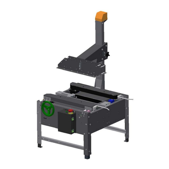
Page 10: Chapter 3: Overview
Chapter Case Sealer Sections Overview This manual covers several parts of the machine. The following diagram identifies the key sections of the machine. Mast Assy. Head Assy. Head Lock Side Belt Drive Side Rail Lock Frame Assy. Side Drive Guides E-stop Control Station/ Electrical Enclosure... - Page 11 Machine Specifications Machine dimensions: Height: 60.81” @ 22.25” conveyor height Width: 42.08” Length: 31.77" Conveyor height: 22.25” to 30.25” – Standard Electrical Requirements: Standard Voltage: 120/1/60 with 15 amp dedicated service. Optional voltages are available consult factory. Operating speed: ...
- Page 12 Air Requirement N/A Machine box capacity: Length: - 6” to infinite Width: - 4.50” to 21” ( 2" tape cartridge) Width: - 5.50" to 21" ( 3" tape cartridge) Height: 4.50” to 20”...
-
Page 14: Chapter 4: Installation
If machine arrives damaged contact Loveshaw immediately to help in filing a claim with shipping company. Section 1: Placing the Machine The case sealer is fully assembled and ready for operation. -
Page 15: Chapter 5: Theory Of Operation
Chapter Theory of Operation LD3SBF The LD3SBF needs to be manually adjusted for the width and height of the box to be sealed. With the machine off, a box will need to be placed between the side belt arms. Rotate the hand wheel to adjust the side belt drives out. - Page 16 Key design features: The LD3SBF is a uniform manual adjusted side belt case sealer with counter balanced head assembly. Some of the key features are. Self tracking industrial grade endless belts. Easy access internal mounted side belt tensioners.
-
Page 17: Chapter 6: Machine Components
Chapter Machine Components Control Station / Electrical Enclosure The control station consist of an electrical enclosure, push pull mushroom head emergency stop switch and a momentary start pushbutton with motor overload relay. START E-STOP... - Page 18 Side Belt Drive Assembly The side drive assembly consist of (2) 1/6 hp gear motor, idler, tension assembly, box guides and endless, guided, rough top belting. The side belt drive assembly, assist in conveying the box forward through the machine. The side belt drive assembly insures that tall unstable boxes will not topple over as they process through the machine.
- Page 19 Head Weldment & Mast Assembly The head weldment assembly consists of a sheet metal weldment, roller bearings, slide plates and locking knob. The weldment can be converted to a 2" wide or 3" wide cartridge cavity by changing the tie shafts. The horizontal surface that contact the box is made of a low friction plastic that provides a long wear surface.
-
Page 20: Chapter 7: Maintenance
Chapter Maintenance Safety: NEVER perform any maintenance on the LD3SBF without first following your company’ s LOCK OUT / TAG OUT procedures. Replacing Side Belt Gear motor 1. Disconnect electrical or unplug machine. 2. Remove side belt drive guard. 3. Loosen belt by turning locking nut on bottom side of belt arm. - Page 21 8. Rewire replacement motor and replace it with the four mounting Replace wire ties on motor cable. Make sure to leave room for side belt to travel in/out. 10. With height note from removal reinstall drive roller and key. 11. Install endless belt and tighten tensioner. DO NOT over tighten this may cause damage to idler assembly or belt.
- Page 22 Machine Maintenance: Daily------- Clean machine ( as required) Inspect side belt drives. Weekly----- Check / Adjust side belt tensioner Inspect area around gear motors Inspect belt idlers Adjust finger guards for belts (as required) Monthly---- Check / Adjust head wear pads Cartridge Maintenance: Refer to cartridge area of manual...
- Page 23 Constant force spring removal and installation 6/20/06 Rev. 1 procedure for internally mounted spring 1 of 3 The following are step by step instructions for the removal and installation of the internally located constant force spring assembly. SPECIAL NOTE: Follow proper lock out/tag out procedures and use proper PPE (personal protection equipment) Example: safety glasses and protective gloves.
- Page 24 Constant force spring removal and installation 6/20/06 Rev. 1 procedure for internally mounted spring 2 of 3 Figure 7: Figure 11: Slide head upward until Reassemble new spring is forced constant force outside of mast. spring assembly. Figure 8: Figure 12: Slide head up to Insert spring shaft expose spring mount...
- Page 25 Constant force spring removal and installation 6/20/06 Rev. 1 procedure for internally mounted spring 3 of 3 Figure 15: Pivot spring in place to line up with spring/actuator bracket and reinstall hardware. Figure 16: Reinstall head stop hardware in mast assembly.
- Page 26 LD3SB B & SP30 04 Side b belt rem moval and d install lation in nstructio on. Step 1: Pr reform Lock O Out / Tag Out procedure. Step 2: C over remova l. move belt arm cover r by screwing c cover hard ware. INTER RNAL PA RT IDEN NTIFICAT TION Drive rolle r ...
- Page 27 LD3SB B & SP30 04 Side b belt rem moval and d install lation in nstructio on. Step 4: R emove belt te ension by los ing jam nut a and turning ja ack stud out f rom idler. acking stud am nut Step 5: A Adjust belt fing ger guard out tward to prov vide room for r belt remova al. Finger guard ...
-
Page 28: Troubleshooting
Chapter Troubleshooting: PROBLEM CAUSE CORRECTIVE ACTION Machine will not start. Emergency stop switch(s) activated either Check that both E-stop switches are not control box or top head assembly. engaged. No incoming power. Check machine fuses and plant receptacle. Defective start pushbutton Re-place pushbutton. - Page 29 1 YEAR ON SERVO DRIVE 1 YEAR ALL OTHER PARTS Except for wear and moving parts. *LIMITED WARRANTY – LOVESHAW, WARRANTS ONLY THAT THE GOODS SOLD BY IT SHALL BE FREE FROM DEFECTS IN MATERIAL AND WORKMANSHIP, UNDER PROPER AND NORMAL USE AND MAINTENANCE,...
- Page 30 INVOLVED IN AN ACCIDENT. NO PERSON IS AUTHORIZED TO MAKE ANY WARRANTY OR TO CREATE ANY LIABILITY BINDING UPON LOVESHAW, WHICH IS NOT STATED IN THIS WARRANTY. THIS WARRANTY IS EXPRESSLY IN LIEU OF ALL OTHER WARRANTIES OF ANY KIND, EXPRESSED OR IMPLIED, WHICH ARE HEREBY EXCLUDED.
- Page 31 Chapter ASSEMBLY DRAWINGS AND SCHEMATICS...
- Page 35 THIS DRAWING AND SUBJECT MATTER THEREON IS THE EXCLUSIVE PROPERTY OF DWG NO SCALE = .3mm METRIC FINISH LOVESHAW-ITW AND IS TO BE TREATED BY YOU AS CONFIDENTIAL PRPRIETARY .XXX = .1mm INFORMATION. THIS DRAWING OR SUBJECT MATTER THEROF SHALL NOT BE MATERIAL NOTED...
- Page 36 LD3S SBF & & SP30 04F M Motor Selec ction C Chart SPECIA AL NOTE: Before e ordering g any side ebelt gear r motors have mac chine Mo odel, Serial N Number a and moto or side loc cation. Th his will he elp determ mine corr...
- Page 41 Chapter MACHINE AVAIABLE SPECIAL OPTIONS...
Need help?
Do you have a question about the LD3SBF and is the answer not in the manual?
Questions and answers