Advertisement
Table of Contents
Advertisement
Table of Contents

Related Manuals for Bioloid Premium Kit

Summary of Contents for Bioloid Premium Kit
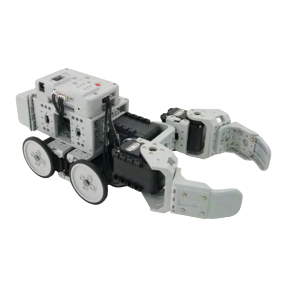
- Page 1 Bioloid Premium Kit Probing Robot Assembly Manual v1.0 ROBOTIS EXCLUSIVE DISTRIBUTOR. RO-BOTICA GLOBAL S.L. C/ Hercegovina 22, bajos 08006 Barcelona (Spain) Bioloid www.ro-botica.com Tel: +34 934 143 581 info@ro-botica.com Premium Kit Probing Robot Assembly manual...
- Page 2 Attention! Before proceeding with assembly, you must ensure each actuator’s horn is properly aligned. To visually verify proper alignment, the notch from the horn should be in line with the notch from the actuator’s body. If not, perform one of the following actions: A.Turn the horn manually un til it is properly aligned.
- Page 3 Bioloid Probing Robot – Getting Started Attach ID5, F2, F3, and F10 together. (Do not misalign horn position.) Attach F1, F9, and F11 together. Attach STEP①, STEP②, ID6, and ID7 together. (Do not misalign horn position.)
- Page 4 Attach STEP③, F3, F54, IR SENSOR, and DMS together. IR SENSOR RIVET 5P CABLE-15 CABLE-DMS 5P CABLE-15 SENSOR SENSOR RIVET 5P CABLE-15 RIVET SENSOR RIVET With 2 CABLE-10, connect ID5 to ID7; ID6 to ID7. Connect ID5 with CABLE-10. CABLE-10 CABLE-10 CABLE-10 CABLE-10...
- Page 5 Attach ID1 through ID4, F3, and F55 together. x 24 x 36 Attach STEP⑥, F13, F14, and F51 together. x 16 Attach F3, F10, and F60 together.
- Page 6 Attach STEP⑤, STEP⑦, and STEP⑧ together. Connect ID4 to ID5 with CABLE-10. With 3 CABLE-6, connect ID2 to ID4; ID1 to ID2; ID1 to ID3. Connect ID 3 with CABLE-20. CABLE-6 CABLE-6 Attach STEP⑨, F52, and CM-510 together. Connect ID3 to CM-510 with CABLE-20. Connect IR SENSOR to Port 2 of CM-510 with 5P CABLE-15.
- Page 7 Connect the battery through the battery cable. BATTERY BATTERY...
- Page 8 Assembly Check After assembly please check the following procedure to ensure correctness. Run the assembly check program Set the robot in PLAY mode; hold the D button then press START. Once the START button is pressed, the assembly check program begins. AX12+ initial position and ID check Select each actuator separately and compare it to the picture below.
Need help?
Do you have a question about the Premium Kit and is the answer not in the manual?
Questions and answers