Table of Contents
Advertisement
Advertisement
Table of Contents

Summary of Contents for SmarTap e-Valve
- Page 1 INSTALLATION GUIDE...
- Page 2 Welcome, Thank you for using SmarTap – an advanced digital shower system. Careful adherence to the installation procedures and maintenance practices set out in this manual will ensure many years of outstanding performance from your new shower. Please note, No part of this publication may be reproduced, stored in a retrieval...
-
Page 3: Table Of Contents
Hydraulic Characteristics ..............14 Installation Options ................15 Plan System Layout ................19 Prepare for Installaiton................19 Prepare Infrastructure .................22 Connect e-Valve and Connect Pipes ..........30 Connect Controllers ................35 Install Power Supply ................37 Connect Cables to e-Valve ..............38 Software Outlets Configuration ............41 Final Inspection ..................42 Maintenace ..................43... -
Page 4: Introduction
Please read and understand this guide before operating the system. It is mandatory to follow the instructions in the guide and the technical description in order to avoid damage to the system. If any part of this guide is not clear, please contact SmarTap Technical Support at support@smartap-tech.com for clarification. -
Page 5: Important Safeguards
INSTALLATION OR USE OF THE PRODUCT THAT IS NOT IN ACCORDANCE WITH THE INSTRUCTIONS SPECIFIED BELOW. NOTE THE CONTENTS OF THIS GUIDE ARE SUBJECT TO CHANGE WITHOUT PRIOR NOTICE. Safety Instructions WARNING DO NOT USE THE E-VALVE SYSTEM BEFORE READING AND UNDERSTANDING THIS GUIDE 3 of 51... - Page 6 WARNING UNAUTHORIZED MODIFICATION MAY CAUSE POOR PERFORMANCE OF THE E-VALVE. DO NOT MAKE MODIFICATIONS TO THE VALVE AS THIS COULD ADVERSELY AFFECT THE PERFORMANCE OF THE VALVE AND VOID THE WARRANTY. SMARTAP WILL NOT BE LIABLE UNDER ITS WARRANTY OR OTHERWISE FOR PERSONAL INJURY OR DAMAGE CAUSED BY AN UNAUTHORIZED MODIFICATION.
- Page 7 WARRANTY CLAIM CAN BE CONSIDERED OR LIABILITY ACCEPTED BY SMARTAP IF LACK OF ACCESSIBILITY HAS PREVENTED MAINTENANCE). CAUTION THE E-VALVE MUST NOT BE INSTALLED IN PLACES WHERE EITHER THE AMBIENT TEMPERATURE IS LIKELY TO EXCEED 40°C OR WHERE FREEZING MAY OCCUR.
-
Page 8: Labels And Symbols
Labels and Symbols The e-Valve system has the following labels and symbols. Symbol Description Read the Installation manual Manufacturer Class III Appliance Read all documents including the User’s Guide IPx6 Water projected by a nozzle (6.3 mm) IPx6 against enclosure from any direction shall have no harmful effects. -
Page 9: Technical Specifications
Technical Specifications Absolute Maximum Ratings 1 – 9 bar Working pressure Overpressure 16 bar Burst pressure 35 bar Hot water temperature 70 C 5 – 60 C Ambient temperature Relative humidity 90% non-condensing Recommended Conditions 2 – 5 bar Working pressure 50 –... -
Page 10: Package Contents
Package Contents The SmarTap Digital Shower system package includes the following components: AC cord length: 1.5m DC cord length: 1.5m e-Valve AC/DC Adaptor 8 of 51... - Page 11 IP67 compatible IP67 compatible (If applicable) One Dial Two Dial controller cable controller cable WARNING IF THE SYSTEM PARTS SHOW ANY KIND OF MECHANICAL DAMAGE, DO NOT USE THE SYSTEM AND CONTACT A SMARTAP REPRESENTATIVE FOR SERVICE. 9 of 51...
-
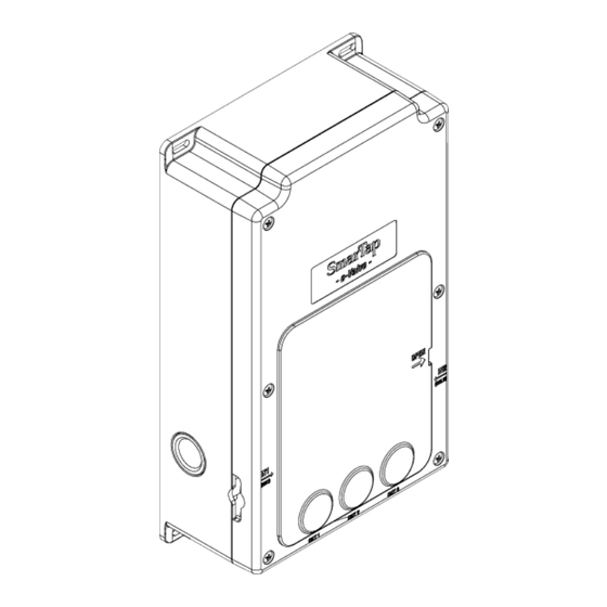
Page 12: System Dimensions & Mechanical Specifications
System Dimensions & Mechanical Specifications e-Valve 10 of 51... - Page 13 Two Dial Controller 11 of 51...
- Page 14 One Dial Controller 12 of 51...
-
Page 15: Tools
Tools For installation of the SmarTap digital shower product, you will need the following tools: (If Applicable) For the One Dial controller, use a 62mm hole saw. 13 of 51... -
Page 16: Hydraulic Characteristics
Hydraulic Characteristics Typical flow rate performance of e-Valve at various inlet and outlet conditions Dynamic pressure [bar] Single outlet, open Single outlet, resistance class C Two or three outlets, open 14 of 51... -
Page 17: Installation Options
Installation Options Shower - Concealed Installation (In wall): Fixed head, Handset, Water Jets WARNING THE POWER CABLE MUST BE SECURED AND CHASED INTO THE WALL. IT MUST NOT BE LEFT EXPOSED TO KEEP IT PROTECTED IN THE EVENT OF A POSSIBLE LEAK. - Page 18 Bath - Concealed Installation (Under bath): Fixed head, Handset, Bath overflow filler WARNING THE POWER CABLE MUST BE SECURED AND CHASED INTO THE WALL. IT MUST NOT BE LEFT EXPOSED TO KEEP IT PROTECTED IN THE EVENT OF A POSSIBLE LEAK.
- Page 19 Shower – Loft Mounted: Fixed head, Handset, Water Jets WARNING THE POWER CABLE MUST BE SECURED AND CHASED INTO THE WALL. IT MUST NOT BE LEFT EXPOSED TO KEEP IT PROTECTED IN THE EVENT OF A POSSIBLE LEAK. PLEASE MAKE SURE THAT THE CABLE IS INSTALLED BY A QUALIFIED ELECTRICIAN.
- Page 20 Bath – Loft Mounted (Under bath): Fixed head, Handset, Bath overflow filler WARNING THE POWER CABLE MUST BE SECURED AND CHASED INTO THE WALL. IT MUST NOT BE LEFT EXPOSED TO KEEP IT PROTECTED IN THE EVENT OF A POSSIBLE LEAK.
-
Page 21: Plan System Layout
2. Prepare installation location for controllers. 3. Prepare installation location for the AC/DC power supply. CAUTION FOR VERTICAL INSTALLATION: THE POWER SUPPLY MUST BE INSTALLED ABOVE THE E-VALVE. Prepare locations for e-Valve unit ,controllers and Power supply Prepare for Installaiton 19 of 51... - Page 22 Pipework Considerations WARNING IF A BOOST PUMP IS USED TO FEED THE E-VALVE, MAKE SURE THAT THE SAME PUMP FEEDS BOTH HOT AND COLD INLET. IT IS STRICTLY PROHIBITED TO FEED ONLY ONE OF THE E-VALVE INLETS BY A BOOST PUMP, OR TO FEED ITS INLETS WITH TWO SEPARATE BOOST PUMPS.
- Page 23 IT IS FORBIDDEN TO WELD DIRECTLY NEXT TO THE UNIT. MINIMUM DISTANCE FROM E-VALVE BODY IS 15CM. USE WETTED RAG TO PREVENT UNIT FROM RECEIVING DIRECT HEAT FROM THE WELDING TORCH 2. Connect the male fitting to the e-Valve terminals. 21 of 51...
-
Page 24: Prepare Infrastructure
Prepare Infrastructure Prepare the Hot and Cold water inlet pipes. Run the outlet applicable pipes from the e-Valve unit to the outlet. NOTE MARK ON EACH PIPE ITS DESIGNATION. CAUTION MAKE SURE THAT THE PIPEWORK IS PERPENDICULAR TO THE E-VALVE SO THAT THERE IS NO STRAIN ON THE FITTINGS. - Page 25 Run the Two Dial control cable from the location of the e-Valve unit to the location of the Two Dial controller – female end on e-Valve side , male end on controller side Use 20mm Electrical conduits. Leave Extra cable at the e-Valve side.
- Page 26 Make a rectangular cut in the tile Use a knife to remove the round according to the dimensions of brackets of the junction box to the Two Dial junction box. enable wiring connection. Remove the one that is closest Height (H) 154 mm to the Conduit cable.
- Page 27 Insert the Two Dial electrical Attach the Two Dial junction junction box into the tile. Press box to the tile with silicone/glue on the box until the outer from the inside. setting touches the tile. CAUTION Apply a thick layer of THE UP ARROW compound to fully seal INSIDE THE BOX...
- Page 28 Insert control cable into the Insert the conduit to the hole. interface of the junction box. Leave a few centimeters inside CAUTION the box. LEAVE 10 CM OF CABLE OUTSIDE THE BOX AND SECURE THE CABLE. Insert cable Connect conduit Finish the tiling of the wall or continue to the next step.
- Page 29 (If applicable) Make a round Use a knife to remove the cut in the tile according to the round brackets of the junction dimensions of the One Dial box to enable wiring junction box. connection. Remove the one that is closest Diameter 62 mm to the Conduit cable.
- Page 30 Insert the One Dial electrical Attach the One Dial junction junction box into the tile. Press box to the tile with silicone/glue on the box until the outer from the inside. setting touches the tile. Apply a thick layer of compound to fully seal CAUTION the internal components.
- Page 31 Insert the control cable into the Insert the conduit to the hole. interface of the junction box. Leave a few centimeters inside CAUTION the box. . LEAVE 10 CM OF CABLE OUTSIDE THE BOX AND SECURE THE CABLE. Insert cable Connect conduit Finish the tiling of the wall or continue to the next step.
-
Page 32: Connect E-Valve And Connect Pipes
Connect e-Valve and Connect Pipes Mount the e-Valve in its location and according to the wall type. Vertical installation Horizontal installation e-Valve installation CAUTION PREWASH THE HOT AND COLD INLET PIPES BEFORE CONNECTING THE PIPES TO THE E- VALVE Prewash inlet pipes... - Page 33 Connect the pipes to the e-Valve, according to the figure below. WARNING MAKE SURE THAT THE HOT/COLD INLET IS CONNECTED TO A WATER INLET BY THE TEXT "IN1 (HOT)"/"IN2 (COLD)" ON THE E-VALVE BOX. 31 of 51...
- Page 34 FOLLOWING ORDER: OUT1 OUT2 OUT3. OUT1 IS THE DEFAULT OUTLET. CONNECT THE DIFFERENT OUTLETS ACCORDINGLY. CAUTION MAKE SURE THAT THE PIPEWORK IS PERPENDICULAR TO THE E-VALVE SO THAT THERE IS NO STRAIN ON THE FITTINGS. Connect outlet pipes 32 of 51...
- Page 35 Connect hot water and cold water inlet pipes. CAUTION MAKE SURE THAT THE PIPEWORK IS PERPENDICULAR TO THE E-VALVE SO THAT THERE IS NO STRAIN ON THE FITTINGS. Connect inlet pipes 33 of 51...
- Page 36 1. Open water main valve. 2. Conduct visual inspection for leaks on the inlet pipes. 3. Close water main valve. Test inlets for leaks Proceed to next step after outlets are installed and tiles attached. 34 of 51...
-
Page 37: Connect Controllers
Connect Controllers Connect the cables to the Two Dial controller: Two Dial controller – e-Valve. Two Dial controller – One Dial controller (If applicable). CAUTION MAKE SURE THAT THE O-RING OF THE JUNCTION BOX IS IN PLACE Connect cables to the Two Dial controller 1. - Page 38 Connect the cables to the Two Dial controller: Two Dial controller – One Dial controller (If applicable). CAUTION MAKE SURE THAT THE O-RING OF THE JUNCTION BOX IS IN PLACE. Connect cables to the One Dial controller 1. Attach the controller to the junction box. 2.
-
Page 39: Install Power Supply
1. Hold the power supply up to the installation location: a. Make sure that the AC cord will reach the electrical outlet. b. Make sure that the DC cord will reach the e-Valve DC cable inlet. CAUTION MAKE SURE THAT YOU HAVE ENOUGH SPARE CABLE FOR MAKING DRIP LOOPS ON BOTH ENDS. -
Page 40: Connect Cables To E-Valve
Connect Cables to e-Valve To remove the e-Valve cover 1. Press on the two red use a flat screwdriver. insert it handles to release the in the designated place and electronics box. twist clockwise. 2. Gently pull out the box. Be careful, other cables are connected to it. - Page 41 1. Insert the cable into the e-Vale through the cable inlet holes on the sides of the e-Valve. 2. Gently connect the cable connector to an applicable interface on the main module. To do so, align the projection of the cable’s connector to the receptacle keyway slot of the interface.
- Page 42 Insert the electronics box gently until you hear the “Click” sound. Insert electronics box 1. Connect the e-Valve power supply into the power plug. 2. Make drip loops on both ends of the power supply cable. Connect e-Valve to electric source Wait until the e-Valve finishes the Internal test.
-
Page 43: Software Outlets Configuration
Software Outlets Configuration Please refer to the enclosed document titled: GUIDELINES FOR PAIRING SMARTAP E-VALVE WITH SMARTPHONE APPLICATION CAUTION IF A SEALED OUTLET IS NOT DISABLED USING A SOFTWARE CONFIGURATION TOOL, THE DEVICE MAY NOT FUNCTION PROPERLY. CAUTION ALL OUTLETS THAT ARE NOT CONNECTED MUST BE PROPERLY SEALED. -
Page 44: Final Inspection
Make sure that the internal and external check-valves (if any) of the inlets are open and the system is pressurized in both inlets. Make sure that the hot water that is supplied to the e-Valve reaches a sufficient temperature (> 40 Operation check: Turn on the system. -
Page 45: Maintenace
If a malfunction occurs or if maintenance is required, the user will be notified by dedicated colors and blinking patterns on the Two Dial and the One Dial controllers. If there is a notification that is not covered in this manual, please contact SmarTap for further assistance. NOTE E-VALVE IS EQUIPPED WITH INTERNAL STOP- VALVES. - Page 46 Backup battery replacement indication When the battery charge level drops below a certain level, the system will notify user when the e-Valve is turned off: the dials will illuminate with a yellow light and the flow dial will blink in an alternating pattern.
- Page 47 To replace the backup battery, do as follows: 1. Disconnect the e-Valve from the main power supply. 2. Remove e-Valve box cover and wait until the internal LED indicator switches off (See Step 30). 3. Remove electronics box (See Step 31).
-
Page 48: Troubleshooting
The flow rate is Make sure that the inlet pressure is sufficient insufficient Consult SmarTap regarding the possibility to service the internal filter The system is Make sure that the inlet pressures are within alternatively stopping... -
Page 49: System Components
Electronics box LED Check connection of all cables, especially the is red sensors cable Return the box back to the e-Valve, close the cover and connect the power supply IF the problem remains, contact SmarTap System Components 47 of 51... -
Page 50: Notices
Notices Warranty Your digital shower system is covered by a manufacturer’s warranty against any defect under normal operational circumstances for 5 years. This warranty covers defects in products or workmanship directly related to this product when installed, maintained and operated in accordance with the instructions supplied. - Page 51 SmarTap Ltd. T/F: +972-74-702-5142 support@Smartap-tech.com www.smartap-tech.com intro.smartap-tech.com 26 Ba’alei Melacha St. Haifa 3223020 Israel April 2017 49 of 51...
Need help?
Do you have a question about the e-Valve and is the answer not in the manual?
Questions and answers
My taps flash red. I replaced the battery but still not working
The SmarTap e-Valve may be flashing red after replacing the battery because the wrong type of battery was used. Only non-rechargeable 9V Lithium batteries are allowed. Rechargeable, alkaline, or carbon zinc batteries must not be used. Using an incorrect battery can cause the system to malfunction.
This answer is automatically generated