Table of Contents
Advertisement
Advertisement
Table of Contents

Related Manuals for um Renegade Commando


Summary of Contents for um Renegade Commando
- Page 1 SERVICE MANUAL BODY – RENEGADE MOTORCYCLE 300 CC...
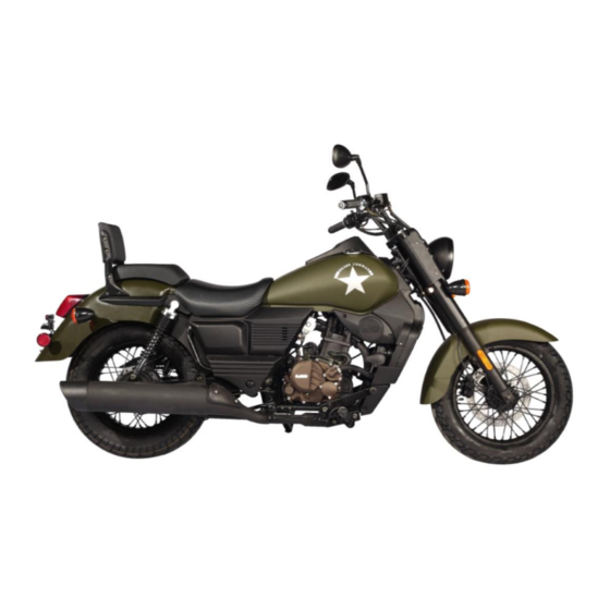
- Page 2 RENEGADE COMMANDO RENEGADE SPORTS...
- Page 3 VEHICLE MAJOR DIMENSIONS...
- Page 4 VEHICLE IDENTIFICATION NUMBER (VIN) VIN number is punched on the Right Side of the Frame, Generally on the Head Tube as shown in the Picture (Yellow marked area).
- Page 5 LOCATION OF IMPORTANT BODY PARTS Storage box Air cleaner Tool box Cushioned backrest Rear fender assembly Rear Wheel Rear Brake panel RH side cover Fuel Tank Chassis...
- Page 6 LOCATION OF IMPORTANT BODY PARTS Radiator Carburetor/Throttle body Battery Rear sprocket & Chain drive Pillion hand hold Main stand Side stand Front wheel & Front fender Front Hydraulic brake assembly Handle bar assembly Front fork assembly...
- Page 7 VEHICLE SPECIFICATIONS RENEGADE RENEGADE GROUP DESCRIPTION COMMANDO SPORTS S FRAME TUBULAR TUBULAR HYDRAULIC HYDRAULIC SUSPENSION – TELESCOPIC D TELESCOPIC D FRONT SUSPENSION 41 MM 41 MM TWIN TWIN SUSPENSION – HYDRAULIC HYDRAULIC REAR WITH SPRING WITH SPRING 172 Kg (with 172 Kg (with KERB WEIGHT 90% fuel* oil)
- Page 8 VEHICLE SPECIFICATIONS RENEGADE RENEGADE GROUP DESCRIPTION COMMANDO SPORTS S WHEEL RIM SIZE – 2.50 x 16 2.75 – 17 FRONT WHEEL RIM SIZE – 3.50 x 15 3.5 – 15 REAR WHEEL RIM & 110 / 90 - 16 110 / 70 - 17 TYRE SIZE –...
- Page 9 DISMENTALLING & ASSEMBLING OF VEHICLE Seat rear & front. Side cover RH Side cover LH Engine decoration covers LH & RH side. Fuel tank. Air cleaner Rear fender Rear sprocket, brake panel & rear wheel Rear swing arm Front wheel Front fender Front fork Steering stem...
- Page 10 1-REAR & FRONT SEAT ASSEMBLY Remove rear seat Remove front seat Flange bolt-M6*16 flange bolts-M6*12*2 No’s (T wrench-10mm) (T wrench-10mm)
- Page 11 2-RIGHT SIDE COVERS RIGHT SIDE COVER Remove Lower side cover RH by unlocking with key. Remove rear side cover RH by pulling out side carefully. Remove 3 pan head screws, M6*16, to remove front side cover RH. Reassembly in the reverse order of removal and disassembly.
- Page 12 3- LEFT SIDE COVERS LEFT SIDE COVER Remove rear side cover LH by pulling out side carefully. Remove 3 screws to remove front side cover M6*16 No’s-Pan head Reassembly in the reverse order of removal and disassembly.
- Page 13 4-ENGINE DECORATION COVER LH & RH SIDE Remove LH & RH side Engine decoration cover. Allen screw M6*16*2 No’s each side (Allen key 4mm) Reassembly in the reverse order of removal and disassembly.
- Page 14 5-FUEL TANK Drain all the petrol from Fuel tank. Disconnect fuel tube from fuel knob. Remove Fuel tank rear side bolt. M8*35 with plain washer- (T Wrench 12mm) Remove rubber cushion. Disconnect fuel gauge & speedometer couplers.
- Page 15 6-AIR CLEANER After removing Fuel tank as per procedure given(Refer- Point 5). AIR FILTER ASSY can be taken out. Flange bolts M6*16*3 No’s (T wrench10mm) Tightening torque-10~12 Nm Remove tool kit box by pulling it outside.
- Page 16 AIR CLEANER ELEMENT CLEANING Remove Rh side cover assembly as per steps given in point number-2. Remove intake pipe by removing 3 screws 20 mm length. Remove air cleaner element for cleaning. CLEAN THE ELEMENT BY AIR. REPLACE IF DAMAGED Reassembly in the reverse order of removal and...
- Page 17 7-REAR FENDER Remove rear seat. Remove storage box screws M5*17*3 No’s. Remove backrest Allen bolt M8*16mm*2 No’s with spring washer (2 each RH & LH side). Tool-Allen key 6mm Loosen RL & LH Rear Shock absorber upper mounting dome nut M10 (T-18).
- Page 18 Remove Rear fender carefully ENSURE THAT REAR FENDER IS REMOVED WITHOUT ANY SCRATCHES ON IT. DISCONNECT ALL THE WIRING FROM REAR FENDER BEFORE REMOVING. Rear fender bracket is mounted on main frame with the help of M6*16*4 bolts. Reassembly in the reverse order of removal and disassembly.
- Page 19 8-REAR SPROCKET, REAR BRAKE PANEL & REAR WHEEL Remove rear brake cam nut. CHECK THAT BRAKE CAM IS WORKING SMOOTHLY, APPLY GREASE IF REQUIRED Remove Brake panel nut from position rod. Remove Rear axle nut M with the help of ring spanners.
- Page 20 Remove rear axle from the wheel. Remove Left bush rear sprocket & Flange Rear wheel carefully from rear wheeling arm. Check damper rear wheel for any damage. Replace if found damaged.
- Page 21 Check Dust seal & bearing (6004RS) for proper fitment & smooth rotation. Replace if found worn out/noisy. Remove right bush rear wheel & Panel rear brake carefully from rear wheel. CLEAN HUB INNER SURFACE & BRAKE LINEAR SURFACE BEFORE REFITTING. REPLACE BRAKE SHOES IF FOUND WORN OUT OR HARD.
- Page 22 CHECK THAT BEARING- (6302/2RS)REAR WHEEL Rh SIDE IS FITTED PROPERLY IN HUB. Reassembly in the reverse order of removal and disassembly.
- Page 23 9-REAR SWING ARM Remove Bolt & nut of swing arm. Bolt-M14*279*1.5 mm Nut-M14 Lock nut. Tightening Torque- 60-70 Nm...
- Page 24 Chain slider bolt-Hexagonal flange-M6*16*2 No’s(upper & lower side). 1. CHECK THAT BOTH SIDES DUST COVER & CHAIN SLIDER ARE FITTED PROPERLY & NOT IN DAMAGED CONDITION. 2. CHECK THAT BOTH SIDE ARMS BUSH ARE IN GOOD CONDITION.THERE SHOULD NOT BE ANY DAMAGE/WERING.
- Page 25 Reassembly in the reverse order of removal and disassembly.
- Page 26 10-FRONT WHEEL Remove Front nut from wheel RH side. Nut-M14(Ring spanner-20/22). Remove axle bolt-M14*268. Tightening Torque- 60~70 Nm. While refitting front wheel check that speedometer sensor is properly fitted in groove. ...
- Page 27 Remove Bush- 28*15*22 (OD*ID*T). CHECK THAT DUST SEAL & BEARING BOTH THE SIDES (6302 2RS) ARE IN GOOD CONDITION. REPLACE IF DAMAGED/WORN...
- Page 28 If bearing is noisy, worn out, should be removed with the help of special tool. Inside there is one spacer & rubber washer to properly locate spacer.
- Page 29 Fitment of both sides bearing with the help of special tool. Replace the disc if worn out & thickness is <4.2 mm. To replace, remove 6 Allen screws. Allen Bolt-M8*25...
- Page 30 While tightening- Apply Loctite 290 before tightening TORQUE- 25~28 Nm...
- Page 31 11-FRONT FENDER Remove bolts on each LH & RH side. Bolt-M6*16*2(2 RH & 2 LH side) T Wrench-10 mm...
- Page 32 12-FRONT FORK Front fork can be removed from vehicle with or without front wheel. Remove STEERING BOLT M14*30 CHROME. TORQUE WHILE TIGHTENING- 60~70 Nm Remove Head light decoration cover side & top screws. Side Allen screws-M6*12*4(both sides-Allen key 4 mm)
- Page 33 Top screws-M6*16*2(Allen key 4 mm). Loosen UPPER TRIPLE CLAMP-M10*30*2 No’s both sides. TIGHTENING TORQUE WHILE ASSEMBLING-30~35 Nm Remove STEERING STEM ASSY HEX BOLT-M10*40*2 both sides. TIGHTENING TORQUE WHILE ASSEMBLING-25~35 Nm.
- Page 34 To remove Head light & decoration cover, remove lower nut-M8*1 No’s. Remove Handle assembly carefully along with upper triple clamp without damaging any other part. Remove upper & lower rubber dust seals from shocker tube cover. Remove both side covers. ...
- Page 35 Remove complete Fork assembly from Steering stem. Reassembly in the reverse order of removal and disassembly.
- Page 36 13-STEERING STEM Remove Stem steering nut carefully. Nut-M25. Tightening torque while assembling-20~22 Nm...
- Page 37 Remove dust proof cover. Remove top upper cone. Remove bearing cage. Now remove complete Steering stem from Chassis Main pipe. TAKE CARE OF STEM THREADING FOR ANY DAMAGE.
- Page 38 WHILE ASSEMBLING, APPLY SUFFICIENT QTY OF GREASE ON BEARING SURFACE Reassembly in the reverse order of removal and disassembly. Complete details of Steering Stem & Suspension Quantit ITEM Description FRONT SUSPENSION-RIGHT Φ41 MATT BLACK FRONT SUSPENSION-LEFT Φ41 MATT BLACK OIL SEAL, FRONT FORK UPPER RUBBER FRONT SUSPENSION φ41×φ47×17 FRONT SUSPENSION UPPER DECORATION COVER-R,MATT BLACK FRONT SUSPENSION UPPER DECORATION COVER-R BASE COLOR...
- Page 39 FRONT SUSPENSION LOWER DECORATION COVER-R BASE COLOR FRONT SUSPENSION LOWER DECORATION COVER-L,MATT BLACK FRONT SUSPENSION LOWER DECORATION COVER-L BASE COLOR FRONT LICENCE PLATE BRACKET-FRONT MATT BLACK FRONT TURNING LIGHT BRACKET COVER FRONT HEADLIGHT BRACKET MATT BALCK STEERING STEM ASSY MATT BLACK CLAMP FOR SPEED SENSER CABLE,UP MATT BLACK CLAMP FOR BRAKE TUBE ,UP MATT BLACK STEERING BOLT M14×1.5 CHROME...
- Page 40 14 - REAR BRAKE PEDAL picture specifications Hexagon Bolt M6-30 nut M6 washer Φ16 spring clip Φ14 Hexagon flange bolt M10*1.25-40 Hexagon flange bolt M10*1.25-20...
- Page 41 BRAKE PLAY/PEDAL POSITION ADJUSTMENT Maintain the Brake Pedal Height as per given specification: • Height from Front Footrest Rubber-65-70mm • Height from the ground-350-355mm...
-
Page 42: Specifications
15 -RADIATOR Drain Complete coolant. Loosen all the coolant hoses before dismounting Radiator specifications Hexagon flange bolt M6*16 Hexagon flange bolt M6*25 self-lock nut M6... - Page 43 16-SIDE & MAIN STAND Check that both the stands are smooth in function. Check spring for proper fitment & Apply Grease if hard in operation. Central stand is tightened with- 1.central stand axle L=130- 2.washer Φ16 3.spring pin Side stand is tightened with- Hexagon flange bolt M10*1.25-35-...
- Page 44 17 - SUB FRAME & ENGINE MOUNTING WITH CHASSIS Before removing Engine from Chassis ensure that- Clutch cable is disconnected from Clutch cover. Magneto & Switch gear indication wires are disconnected from wiring harness. Coolant is totally drained from engine & radiator. ...
- Page 45 SUB FRAME & ENGINE MOUNTING WITH CHASSIS...
- Page 46 SUB FRAME & ENGINE MOUNTING WITH CHASSIS specifications Torque Hexagon flange bolt M10*1.25-110 self-lock nut M10*1.25 55~65 Nm Allen Bolt M8-60 self-lock nut M8 28~32 Nm Hexagon flange bolt M8-60 self-lock nut M8 28~32 Nm M6*20 Allen Bolt M10*1.25-30 Hexagon nut M10*1.25 55~65 Nm Hexagon flange bolt M8-90 Self-lock nut M8...
- Page 47 SERVICE MANUAL VER. B170626...
Need help?
Do you have a question about the Renegade Commando and is the answer not in the manual?
Questions and answers