Table of Contents
Advertisement
Quick Links
Advertisement
Table of Contents

Summary of Contents for Maxon SD-274
-
Page 1: User Manual
SD-270 Series Data Radio User Manual January 2017... - Page 2 RF interference with the most requested mechanical footprint in the industry. Should you have questions regarding the operation of the radio, please consult us at: Maxon America, Inc. Phone: 913-859-9515 11535 W. 83 Terrace Email: maxon@maxonamerica.com...
- Page 3 Features CE, FCC, MRC & AS/NZS 4295: 2015 certified Programmable 16 channels (Dip Switch Select) External Software Channel Steering Configurable Power Save Feature FSK, 4FSK& GMSK Modem Options; Supports 19200 bps Frequency Step 6.25KHz CTCSS/DCS Encode/Decode ...
-
Page 4: Specifications
Specifications GENERAL V: 136-174 MHz U0: 400-440 MHz Working Frequency U1: 430-470 MHz U2: 450-490 MHz Channel Spacing 12.5KHz/25KHz Programmable Modulation Type F3D/F3E Number of Channels Nominal Working Voltage 12V DC Extreme Working Voltage 9.6 V~16V DC Storage Temperature -40℃~+80℃ Operating Temperature -30℃~+65℃... -
Page 5: Transmitter Specification
TRANSMITTER Specification RF Power 1W/2W/3W/4W/5W Programmable 25KHz Channel Spacing <5KHz Frequency 12.5KHz Channel Spacing <2.5KHz Deviation Subsonic 0.5KHz 25KHz Channel Spacing 300Hz~3KHz +1/-3dB Audio Response 12.5KHz Channel Spacing 300Hz~2.55KHz +1/-3dB Adjacent 25KHz Channel Spacing <-70dBc Channel Power 12.5KHz Channel Spacing <-65dBc <1GHz,<-36dBm Conducted Spurious Emission... -
Page 6: Exterior View
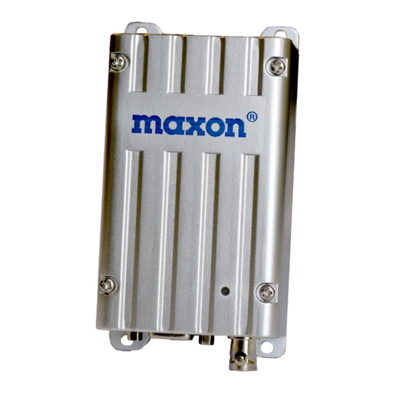
IF Rejection >70dB Spurious Rejection >70dB Intermodulation Suppression >65dB Conducted Spurious Emission <-57dBm Receiving Audio Distortion <5% 25KHz Channel Spacing >45dB RX SNR 12.5KHz Channel Spacing >40dB Audio Output Power 0.5W @ 8Ωload Exterior View Description of radio components ① DB15 Female connector ②... - Page 7 SD-270 External DB15 female Pin Assignment SD-270 Series is manufactured by default with modem, if the radio does not have a built-in modem; the corresponding pin is defined as empty. Function Description Note ① AUDIO_IN Audio input, 3Khz LPF, Modulation AUDIO_IN is effective only (MOD IN)...
-
Page 8: Antenna Installation
⑧ PROG Programming data input, 5V TTL (DATA IN) AUDIO_IN is effective only ⑨ SPK: Audio output from the audio when PIN7 (MIC) is vacant or amplifier, @ 8Ω. SPK/POCSAG with +5V high level. 3KHz POCSAG: To transmit POCSAG code. LPF filter existed in audio Jumper selectable. -
Page 9: Channel Scan
SQ (Squelch) Level Six SQ levels are set in the radio and can be selected by PC software. The audio signal will continuously transmit. Levels are shown as below: Level 0 is for fully open mute. Level 1:0.15uV Level 2:0.25uV Level 3:0.35uV Level 4:0.45uV Level 5:0.55uV... -
Page 10: Channel Select
3 ---------priority scan, carry with tone Channel Select 16 channels can be selected by inner dip (4) switch (HW) on power board or serial command inputted from our PC software (SW). Only in SW control mode, channel can be selected by PC software in “Channel” feature. Channel Dip Switch Chart TX Protection This feature, when enabled, limits the amount of time that the radio can... -
Page 11: Power Save Mode
volume for the connected speaker in set in the programming. The default volume is 6. The minimal volume is 0 and the maximum is 9. Power Save Mode When user enables the function, The SD-270 will operate in a status to lower power consumption in standby. -
Page 12: Parameter Programming
Parameter Programming The SD-274 is configured before leave factory, the user can directly use. If the parameters of the radio need to be modified, refer to the programming software and manual. Modem Option for Data Communication DTE: Data Terminal Equipment... - Page 13 improve the efficiency for data transmission and provide maximum flexibility for user applications. The internal modem options consist of MCU, Modem IC, and extra circuitry. These option-boards directly communicate with DTE to send and receive meaningful data through the DB15 female connector. These modems are designed to accept RS232, RSTTL or RS485 serial data format and are also capable of high speed wireless data-transmission between two or more devices.


Need help?
Do you have a question about the SD-274 and is the answer not in the manual?
Questions and answers