Fritsch PULVERISETTE 19 Operating Instructions Manual
Universal cutting mill
Hide thumbs
Also See for PULVERISETTE 19:
- Operating instructions manual (62 pages) ,
- Assembly instructions manual (24 pages) ,
- Operating instructions manual (64 pages)

Related Manuals for Fritsch PULVERISETTE 19


Summary of Contents for Fritsch PULVERISETTE 19
-
Page 1: Operating Instructions
Operating instructions UNIVERSAL CUTTING MILL PULVERISETTE 19 Valid starting with: 19.10xx/0100 Read the instructions prior to performing any task! Translation of the original operating instructions... - Page 2 Fritsch GmbH Milling and Sizing Industriestraße 8 55743 Idar-Oberstein Telephone: +49 (0)6784/ 70-0 Fax: +49 (0)6784/ 70-11 Email: info@fritsch.de Internet: www.fritsch.de Version 09/2014 Index 010...
- Page 3 Certifications and CE conformity Certification Fritsch GmbH has been certified by the TÜV-Zertifizierungsgemeinschaft e.V. An audit certified that Fritsch GmbH conforms to the requirements of the DIN EN ISO 9001:2008. CE Conformity The enclosed Conformity Declaration lists the guidelines the FRITSCH instrument conforms to, to be able to bear the CE mark.
-
Page 4: Table Of Contents
Table of contents Table of contents Basic structure................7 Safety information and use............9 2.1 Requirements for the user............. 9 2.2 Scope of application............... 9 2.2.1 Operating principle............10 2.3 Obligations of the operator..........10 2.4 Information on hazards and symbols used in this manual. . 11 2.5 Device safety information............ - Page 5 Table of contents Initial start-up................25 5.1 Before switching on for the first time........25 5.2 Switching on................. 26 5.3 Function check..............26 5.4 Switching off................ 27 Using the device................28 6.1 Preparing a comminution............ 28 6.1.1 Opening the cutting mill........... 28 6.1.2 Inserting / changing the fixed knives........
- Page 6 Table of contents Index..................... 60 - 6 -...
-
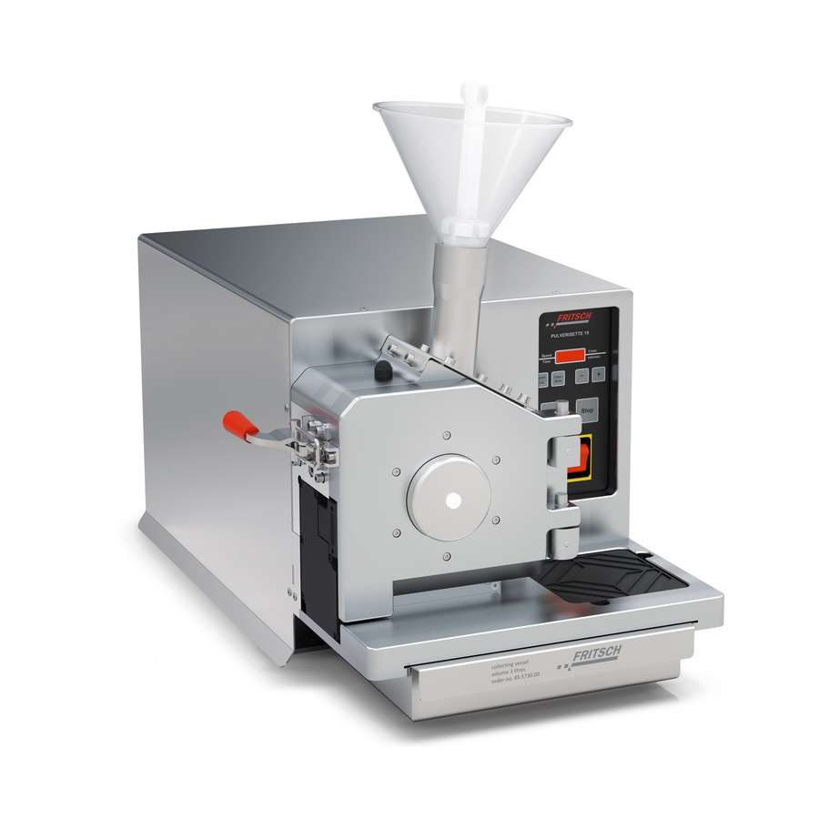
Page 7: Basic Structure
Basic structure Basic structure Standard funnel Fixed knife 2 Upper part of housing Lower part of housing Rotor Lock Fixed knife 1 U-profile Fixed knife 2 Latch clamp Closing lid Motor cover Sieve cassette Safety switch Collecting vessel 15* Safety switch bracket - 7 -... - Page 8 Basic structure Standard funnel 22 Protected funnel 14 Motor cover 23 Plunger (protected funnel) 18 Ventilation grid 24 Sample pusher 19 Control switch 26 Plunger (standard funnel) 20 Mains plug 34 Start button 21 Funnel lid 35 Stop button - 8 -...
-
Page 9: Safety Information And Use
People with health problems or under the influence of medication, drugs, alcohol or exhaustion must not operate this device. The PULVERISETTE 19 may only be operated by authorised persons and serviced or repaired by trained specialists. All commissioning, mainte- nance and repair work may only be carried out by technically qualified personnel. -
Page 10: Operating Principle
For fine comminution, the sample exhaust system can be used with cyclone separator (optional accessory 45.5900.00). 2.3 Obligations of the operator Before using the PULVERISETTE 19, this manual is to be carefully read and understood. The use of the PULVERISETTE 19 requires technical knowledge; only commercial use is permitted. -
Page 11: Information On Hazards And Symbols Used In This Manual
Safety information and use The applicable accident prevention guidelines must be complied with. Generally applicable legal and other obligatory regulations regarding environmental protection must be observed. 2.4 Information on hazards and symbols used in this manual Safety information Safety information in this manual is designated by symbols. Safety infor- mation is introduced by keywords that express the extent of the hazard. - Page 12 Safety information and use DANGER! This symbol and keyword combination designates contents and instructions for proper use of the machine in explosive areas or with explosive substances. Ignoring information with this designation will result in serious or fatal injury. DANGER! This symbol and keyword combination designates contents and instructions for proper use of the machine with com- bustible substances.
-
Page 13: Device Safety Information
Safety information and use Tips and recommendations This symbol emphasises useful tips and recommendations as wells as information for efficient operation without mal‐ function. Further designations To emphasise procedure instructions, results, lists, references and other elements, the following designations are used in this manual: Designation Explanation Step-by-step procedure instructions... -
Page 14: Protective Equipment
European directives and void the guar- antee. Only use the PULVERISETTE 19 when it is in proper working order, as intended and in a safety- and hazard-conscious manner adhering to the operating manual. In particular, immediately rectify any malfunc- tions that could pose a safety hazard. -
Page 15: Opening The Cutting Mill Without Mains Connection
Safety information and use 2.6.1 Opening the cutting mill without mains connection DANGER! The lock must only be released manually when the closing lid is closed. The latch clamp of the door must be locked! Insert the supplied triangular key into the bore hole under the safety lock (11) and turn it clockwise. -
Page 16: Electrical Safety
Safety information and use When opening the upper part of the housing (2), there is an initial resistance. Make sure that the closing lid (6) is fully open! When opening the upper part of the housing (2), slowly swivel it open until the upper part of the housing (2) is resting on the rubber buffer - do not let it fall down heavily. -
Page 17: Protection Against Restart
Safety information and use 2.8.2 Protection against restart In the case of power failure during operation or after switching off with the control switch (19), the closing lid (6) is locked. The lock (11) is opened when power returns. However, for safety reasons the cutting mill does not restart. -
Page 18: Technical Data
Technical data Technical data 3.1 Dimensions 440 mm x 550 mm x 630 mm (width x depth x height) 3.2 Weight 56 - 65 kg (net) 86 - 95 kg (gross) 3.3 Operating noise The noise level is approx. 78 dB (A) when idle and 95 dB (A) when idle incl. -
Page 19: Motor Shaft Power In Accordance With Vde 0530, En 60034
Technical data 3.7 Motor shaft power in accordance with VDE 0530, EN 60034 2.2 kW for 400V / 3~ motor 1.5 kW for 400V / 3~ motor 1.5 kW for 230V / 1~ motor 1.1 kW for 100-120V / 1~ motor 3.8 Electrical fuses Circuit breaker in device Micro-fuse in device... -
Page 20: Installation
Installation Installation 4.1 Transport Transport on transport palette with a forklift or pallet truck. When lifting the device hold it underneath at the back and front only. Do not lift it using the plastic cover. CAUTION! When lifting off, at least 2 persons are required! 4.2 Unpacking Pull out the nails that fasten the crate to the transport pallet. -
Page 21: Fastening The Universal Cutting Mill
Installation 4.5 Fastening the Universal Cutting Mill Screw the cutting mill tightly to the stand provided (acc. to instructions) or to a stable mount (table...). The following must be observed in order to fasten the device: Unscrew the 3 screws fastening the motor cover (14). Lift the motor cover (14) off carefully. -
Page 22: Converting From Standard Funnel To Protected Funnel
Installation 4.6.2 Converting from standard funnel to protected funnel Close the cutting mill. Switch the control switch (19) on the back of the device to 0. Remove the mains plug (20). Unscrew the four M6x12 hexagon bolts fastening the standard funnel (1) to the upper part of the housing (2) using a hexagon socket screw key and lift off the standard funnel (1). -
Page 23: Converting From Protected Funnel To Standard Funnel
Installation 4.6.3 Converting from protected funnel to standard funnel Close the cutting mill. Close the funnel lid (21). Switch the control switch (19) on the back of the device to 0. Remove the mains plug (20). Unscrew the four M6x12 hexagon bolts fastening the protected funnel (22) to the upper part of the housing (2) using a hexagon socket screw key and lift off the protected funnel (22). -
Page 24: Electrical Connection
Installation 4.7 Electrical connection Before establishing the connection, compare the voltage and current values stated on the type plate with the values of the mains system to be used. (see Ä ‘Technical data’ on page 18). If the STOP button lights up red after connection to a three-phase power system and switching the control switch (19) to AUTO, the direc- tion of rotation must be corrected. -
Page 25: Initial Start-Up
Initial start-up Initial start-up 5.1 Before switching on for the first time Connect the device to the mains with the mains plug (20). Switch the control switch (19) on the back of the device to AUTO. The START button must light up green. If the STOP button lights up red, see Ä... -
Page 26: Switching On
Initial start-up Remove the hexagon socket screw key again! If the rotor (3) is not turning freely, proceed as described in Ä ‘Setting the gap width of the knives’ on page 31. NOTICE! This check must also be carried out every time the rotor (3), the fixed knives (4, 5, 9) and the sieve cas- sette (7) are changed! 5.2 Switching on... -
Page 27: Switching Off
Initial start-up 5.4 Switching off Press the STOP button to switch off the device. After waiting a few sec- onds the closing lid (6) can be opened. Switch off the main switch (19) if the cutting mill is to be idle for a longer period of time (e.g. -
Page 28: Using The Device
Using the device Using the device WARNING! If the grinding elements used are not original accessories, we provide no guarantee and exclude all liability for damage to the device. CAUTION! A maximum of 20 starts per hour are permitted for the Uni- versal Cutting Mill with a 230 V and 110 V single-phase motor. -
Page 29: Inserting / Changing The Fixed Knives
Using the device Make sure that the closing lid (6) is fully open! Slowly swivel open the upper part of the housing (2) until it is resting on the rubber buffer. 6.1.2 Inserting / changing the fixed knives Open the cutting mill (see Ä... -
Page 30: Installation Position Of The Fixed Knives
Using the device 6.1.2.1 Installation position of the fixed knives (9) Fixed knife 2 (5) Fixed knife 2 (4) Fixed knife 1 6.1.2.2 Installation position of the fixed knives with tungsten carbide cutting edge (9) Fixed knife 2 (4) Fixed knife 1 (5) Fixed knife 2 NOTICE! Note the position of the Tungsten Carbide hard metal... -
Page 31: Setting The Gap Width Of The Knives
Using the device 6.1.3 Setting the gap width of the knives The knife gap is set at the factory to approx. 0.2 mm. Open the cutting mill (see Ä ‘Opening the cutting mill’ on page 28) but set the control switch (19) on the back of the device to HAND. Loosen the middle retaining screws (A) on all 3 fixed knives (4, 5, 9) and unscrew them slightly. -
Page 32: Inserting / Changing A Rotor
Using the device 6.1.4 Inserting / changing a rotor CAUTION! Risk of injury! Beware of the sharp edges of the rotor! Wear safety gloves when changing the rotor! Open the cutting mill (see Ä ‘Opening the cutting mill’ on page 28). Pull the rotor (3) forwards, wearing safety gloves. -
Page 33: Inserting / Changing A Sieve Cassette
Using the device Push the rotor (3) onto the rotor holder. Turn it clockwise until it engages in the 4 driving pins (C) on the back. (The control switch (19) must be at AUTO) Close the cutting mill (see ). NOTICE! Check if the rotor is turning freely (see Ä... -
Page 34: Closing The Cutting Mill
Using the device 6.1.6 Closing the cutting mill Before closing the cutting mill, clean the cutting chamber, the con- tact surfaces of the housing and, in particular, the locking surfaces of the lock. Swivel the upper part of the housing (2) slowly closed until it is resting on the lower part of the housing (10). -
Page 35: Comminution Procedure With Standard Funnel
Using the device Remove the hexagon socket screw key again immediately! If the rotor is not turning freely, proceed as described in Ä ‘Setting the gap width of the knives’ on page 31. NOTICE! Perform this test each time the rotor or fixed knife is changed, and after a gap adjustment! 6.2 Comminution procedure with standard funnel CAUTION! -
Page 36: Using The Plunger
Using the device 6.2.1 Using the plunger The plunger has 2 different sides for feeding the sample material in the funnel to the grinding chamber. On the one hand, the smooth, round side is suitable for finer material. On the other hand, the cross-shaped, thinner side is suitable for long, fibrous material, like straw. -
Page 37: Overload Of The Cutting Mill
Using the device When the operating noise becomes quieter, the cutting procedure is complete. ð More comminution material can be added in. 6.4 Overload of the cutting mill When filling and making downward movements with the plunger (23) the working noise must be observed. The sound level is nearly identical to the load on the machine. - Page 38 Using the device Press the blue Reset switch. This must be set to "H". Replace the motor cover (14) and screw it tight. Connect the device again to the mains. Switch the control switch (19) on the back of the device to AUTO. ð...
-
Page 39: Sample Exhaust System With Cyclone Separator
Using the device 6.5 Sample exhaust system with cyclone separator CAUTION! Hearing damage! Wear hearing protection during sample extraction with the cyclone separator! (Optional accessory order number: 45.5900.00) The sample exhaust system with cyclone separator can be used for fine comminution. - Page 40 Using the device Attach one end of the connection hose (28) with the rubber sleeve (29) to the adapter (27) and the other end to the cyclone sepa- rator (30). NOTICE! There are 2 opposing hose connections on the cyclone separator (30). Do not use the sealed con- nection;...
- Page 41 Using the device The sample exhaust system is recommended especially in combination with the standard funnel (1) for bulk and long solids. - 41 -...
-
Page 42: Cleaning
Cleaning Cleaning 7.1 Housing The cutting mill can be wiped down with a damp cloth when it is switched off. Disconnect the mains plug (20) from the electricity. DANGER! Do not allow any liquids to flow into the device. 7.2 Cutting chamber Clean the cutting chamber with a dust exhaust system and brush and also with compressed air, if necessary. -
Page 43: Funnel
Cleaning Slowly swivel open the upper part of the housing (2) with the closing lid (6) fully open, until it is resting on the rubber buffer. Clean the cutting chamber. 7.3 Funnel Clean the funnels (1, 22) with a dust exhaust system and brush and also with compressed air, if necessary. -
Page 44: Protected Funnel
Cleaning 7.3.2 Protected funnel Switch the control switch (19) on the back of the device to 0. Pull the sample pusher (24) out of the protected funnel (22) until it stops and fasten it with knurled screw (A). Open the funnel lid (21). Clean the protected funnel (22) from above. -
Page 45: Removing The Plunger
Cleaning 7.3.2.2 Removing the plunger Open the funnel lid (21). Unscrew the cross-head screws (D) with a screwdriver. Close the funnel lid (21). Unscrew the Torx screws (E) with a screwdriver. Unscrew the knurled screw (B). The plunger (23) can be taken out. Install in reverse order. -
Page 46: Sample Exhaust System With Cyclone Separator
Cleaning NOTICE! Make sure that the parts sit firmly when assembling. 7.5 Sample exhaust system with cyclone separator The exhaust system can be disassembled and cleaned after opening the clips (F). To open and clean the cyclone separator, 4 screws in the inner part of the base must be loosened. -
Page 47: Maintenance
Maintenance Maintenance DANGER! Mains voltage – Before beginning with maintenance work, unplug the mains plug and protect the device against being unin- tentionally switched back on again! – Indicate maintenance work with warning signs. – Maintenance work may only be performed by special- ised personnel. - Page 48 Maintenance 25 Exhaust filter Filter holder Filter foam mat Function / Func- Task Test Maintenance interval tional part Exhaust filter (25) Filtering exhaust air Clean exhaust filter (25). To do this, lever out Before every commi- the filter holder (A) with a screwdriver or nution similar.
- Page 49 Maintenance Function / Func- Task Test Maintenance interval tional part Cutting gap Cutting procedure Measure gap width. For setting see Ä ‘Set‐ Whenever rotor and fixed knives are ting the gap width of the knives’ on page 31. changed Cones Centring rotor (3) Check cones for cleanliness and grooves.
- Page 50 Maintenance - 50 -...
- Page 51 Maintenance - 51 -...
-
Page 52: Repairs
Repairs Repairs DANGER! Mains voltage! – Before beginning with repair work, unplug the mains plug and protect the device against being unintention- ally switched back on. – Indicate repair work with warning signs. – Repair work may only be performed by specialised per- sonnel. - Page 53 Repairs Fault description Cause Remedy Runs unevenly with strong Rotor imbalance Cones soiled (see Ä ‘Inserting / changing a vibrations rotor’ on page 32) Bearing in closing lid (6) defective Replace bearing Pieces broken off rotor (3) Replace rotor (3) ( Ä...
-
Page 54: Disposal
FRITSCH declares it is prepared to take back used FRITSCH devices for recycling or disposal free of charge whenever a new device is purchased. The used FRITSCH device must be delivered free of charge to a FRITSCH establishment. In all other cases FRITSCH takes back used FRITSCH devices for recycling or disposal only against payment. -
Page 55: Guarantee Terms
Guarantee terms Guarantee period As manufacturer, FRITSCH GmbH provides – above and beyond any guar- antee claims against the seller – a guaranty valid for the duration of two years from the date of issue of the guarantee certificate supplied with the device. - Page 56 Any servicing done by persons not authorised by us and any use of parts that are not original FRITSCH accessories and spare parts will void the guar- antee.
-
Page 57: Exclusion Of Liability
FRITSCH GMBH distributor or Fritsch GmbH, Industriestr. 8, D-55743 Idar-Oberstein. FRITSCH GMBH takes the greatest care to ensure that the quality, relia- bility and safety of your products are continuously improved and adapted to the state of the art. The supplied products as well as this operating manual conform to the current state of the art when they leave the sphere of influence of FRITSCH GMBH. - Page 58 Exclusion of liability Fritsch GmbH excludes any liability, warranty, or other obligation to com- pensate for damages, regardless of whether this liability, warranty, or other obligation is explicit or implicit, contractual or arising from unlawful acts or prescribed contractually, by law, or otherwise. In no...
-
Page 59: Safety Logbook
Safety logbook Safety logbook Date Maintenance / Repair Name Signature - 59 -... - Page 60 Index Index Accident prevention ......9 Mains voltage ......18 Authorised persons .
-
Page 62: Industriestraße
© 2014 Fritsch GmbH Milling and Sizing Industriestraße 8 55743 Idar-Oberstein Telephone: +49 (0)6784/ 70-0 Fax: +49 (0)6784/ 70-11 Email: info@fritsch.de Internet: www.fritsch.de...
Need help?
Do you have a question about the PULVERISETTE 19 and is the answer not in the manual?
Questions and answers