Table of Contents
Advertisement
Instruction Manual
D101351X012
Fisherr 646 Electro-Pneumatic Transducer
Contents
. . . . . . . . . . . . . . . . . . . . . . . . . . . . . . . . .
. . . . . . . . . . . . . . . . . . . . . . . . . . . . .
. . . . . . . . . . . . . . . . . . . . . . . . . . . . . . . . .
. . . . . . . . . . . . . . . . . . . . . . . . . . . . . . .
. . . . . . . . . . . . . . . . . . . . . . . . .
. . . . . . . . . . . . . . . . . . . . . . . . . . . . . . . . . .
. . . . . . . . . . . . . . . . . . . . . . . . . . . . . . . . . . . .
FM
. . . . . . . . . . . . . . . . . . . . . . . . . . . . . . . . . . . . .
. . . . . . . . . . . . . . . . . . . . . . . . . . . . . . . . . . .
. . . . . . . . . . . . . . . . . . . . . . . . . . . . . . . . . . .
. . . . . . . . . . . . . . . . . . . . . . . . . . . . . . . . . .
. . . . . . . . . . . . . . . . . . . . . . . . . . . . . . . . . .
. . . . . . . . . . . . . . . . . . . . . . . .
. . . . . . . . . . . . . . . . . . . . . . . . . . . . . . . .
. . . . . . . . . . . . . . . . . . . . . . . .
. . . . . . . . . . . . . . . . . . . . . . . . . . . . . . . .
. . . . . . . . . . . . . . . . . . . . . . . . . . . .
. . . . . . . . . . . . . . . . . . . . . . . . . .
Introduction
Scope of Manual
This instruction manual provides installation, operation, maintenance, and parts ordering information for the Fisher
646 transducer. Refer to separate manuals for instructions covering equipment used with the transducer.
Do not install, operate or maintain a 646 electro-pneumatic transducer without being fully trained and qualified in
valve, actuator and accessory installation, operation and maintenance. To avoid personal injury or property damage it
is important to carefully read, understand, and follow all of the contents of this manual, including all safety cautions
and warnings. If you have any questions about these instructions, contact your Emerson Process Management sales
office before proceeding.
www.Fisher.com
. . . . . . . . . . .
. . . . . . . . . . . . . . . . . . . . . .
. . . . . . . . . . . . .
. . . . . . . . . . . . . . . . . .
. . . . . . . . . . . . . . . . . . . . . . .
. . . . . . . . . . . . . . . . . . . . .
. . . . . . . . . . . . . . . . . . . .
. . . . . . . . . . . . . .
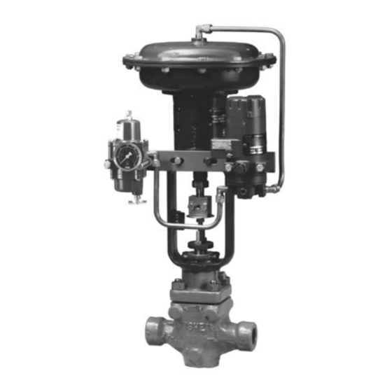
Figure 1. Fisher 646 Electro-Pneumatic Transducer
Mounted on a Sliding-Stem Actuator
1
1
3
4
4
4
5
5
6
6
7
8
9
9
10
10
10
12
12
W6783-1/IL
12
12
13
14
14
. . . . . . . . . . . . . . . . . . . . . . . . . . . . . . . . . . .
15
. . . . . . . . . . . . . . . . . . . . . . . . . . . . . . . . . . .
16
646 Transducer
. . . . . . . . . . . . . . . . . . . . . . . . . . . . . . .
. . . . . . . . . . . . . . . . . . . . . . . . . . . . .
January 2015
18
18
18
22
Advertisement
Table of Contents

Subscribe to Our Youtube Channel
Related Manuals for Emerson Fisher 646


Summary of Contents for Emerson Fisher 646
-
Page 1: Table Of Contents
To avoid personal injury or property damage it is important to carefully read, understand, and follow all of the contents of this manual, including all safety cautions and warnings. If you have any questions about these instructions, contact your Emerson Process Management sales office before proceeding. - Page 2 KGS— Korea Gas Safety Corporation (South Korea) deadband Independent Linearity: ±0.5% of full scale output span Contact your Emerson Process Management sales Hysteresis: 0.4% of full scale output span office for classification/certification specific Frequency Response: Gain is attenuated 3 dB at 10 Hz...
-
Page 3: Description
150 kHz to 80 MHz at 3 Vrms 1. A = No degradation during testing. B = Temporary degradation during testing, but is self‐recovering. Specification Limit = +/‐ 1% of span. Figure 2. Output‐Time Relationships for Fisher 646 Transducer LOADING EXHAUSTING... -
Page 4: Specifications
Should you need an instrument for use with natural gas, Fisher 846 and i2P‐100 electro‐pneumatic transducers both meet third party approvals for use with natural gas as the supply medium. Contact your Emerson Process Management sales office for information on these products. -
Page 5: Hazardous Area Classifications And Special Instructions For "Safe Use" And Installation In Hazardous Locations
Special instructions are listed by approval. Note This information supplements the nameplate markings affixed to the product. Always refer to the nameplate itself to identify the appropriate certification. Contact your Emerson Process Management sales office for approval/certification information not listed here. WARNING Failure to follow these conditions of “safe use”... -
Page 6: Atex
Instruction Manual 646 Transducer January 2015 D101351X012 Intrinsically Safe, Explosion proof, Type n Non‐incendive, Dust‐Ignition proof No special conditions for safe use. Refer to table 4 for additional information. Table 4. Hazardous Area Classifications—FM (United States) Certification Body Certification Obtained Entity Rating Temperature Code Intrinsically Safe... -
Page 7: Iecex
Instruction Manual 646 Transducer D101351X012 January 2015 D If using a rigid conduit connection, an Ex d certified sealing device such as a conduit seal with setting compound shall be provided immediately to the entrance of the enclosure. For ambient temperatures over 70_C, the wiring and setting compound in the conduit seal shall be suitable for at least 90_C. -
Page 8: Mounting
Instruction Manual 646 Transducer January 2015 D101351X012 Type n WARNING Disconnect power before opening. -40_C ≤ Ta ≤ +71_C ; T6 (Ta ≤ +71_C) Refer to table 6 for additional information. Table 6. Hazardous Area Classifications—IECEx Certificate Certification Obtained Entity Rating Temperature Code Ui = 30 VDC Intrinsically Safe... -
Page 9: Pneumatic Connections
40 micrometers in diameter will suffice in most applications, check with an Emerson Process Management field office and industry instrument air quality standards for use with corrosive air or if you are unsure about the proper amount or method of air filtration or filter maintenance. -
Page 10: Diagnostic Connections
Typical connector installations are shown in figure 4. The hardware used includes a 1/4 NPT pipe nipple and pipe tee with a 1/8 NPT pipe bushing for the connector. The connector consists of a 1/8 NPT body and body protector. Figure 4. Diagnostics Hookup for the Fisher 646 Transducer STEM... - Page 11 Instruction Manual 646 Transducer D101351X012 January 2015 For explosion‐proof Class 1, Division 1 applications using metal conduit, install a conduit seal no more than 457 mm (18 inches) from the transducer. Personal injury or property damage may result from explosion if the seal is not installed. For other explosion‐proof applications, install the transducer in accordance with applicable codes.
-
Page 12: Operating Information
Instruction Manual 646 Transducer January 2015 D101351X012 Figure 7. Zero and Span Adjustments and Terminal Block Connections (Cap Removed) PRINTED WIRING ZERO ADJUSTMENT BOARDS SPAN ADJUSTMENT FIELD WIRING CONNECTION − TRANSDUCER HOUSING A3876‐2/IL Operating Information The normal mode of operation for the 646 transducer requires that the pneumatic output pressure be piped to the final control element. -
Page 13: Principle Of Operation
The nozzle pressure provides the input signal to operate the relay as shown in figure 8. Relay output pressure is applied, through tubing, directly to the final control element or valve/actuator assembly. Figure 8. Fisher 646 Transducer Schematic COIL MAGNET... -
Page 14: Maintenance
WARNING The presence of Emerson Process Management personnel and approval agency personnel may be required if you service (other than normal, routine maintenance, such as calibration) or replace components on a 646 transducer that carries a third‐party approval. -
Page 15: Converter Module Replacement
Instruction Manual 646 Transducer D101351X012 January 2015 Electrical 1. Ensure terminal lug connections from the control device to the transducer are of the correct polarity (refer to the electrical connection procedures in the Installation section). 2. At the transducer, ensure that the milliampere DC signal is applied and that it is within the 4 to 20 milliampere range. -
Page 16: Relay Maintenance
Instruction Manual 646 Transducer January 2015 D101351X012 Relay Maintenance Refer to figure 10 for key number locations. Removal 1. Remove the four mounting screws (key 7) and remove the relay from the transducer. Be careful not to lose the bias spring (key 13) and input diaphragm (key 9). - Page 17 Instruction Manual 646 Transducer D101351X012 January 2015 2. Insert the assembled valve plug, inner valve spring, and body plug into the relay body (key 1). Compress the spring and thread the body plug (key 5) into place. Then, tighten the body plug. 3.
-
Page 18: Parts Ordering
Use only genuine Fisher replacement parts. Components that are not supplied by Emerson Process Management should not, under any circumstances, be used in any Fisher instrument. Use of components not supplied by Emerson Process Management may void your warranty, might adversely affect the performance of the instrument, and could result in personal injury or property damage. - Page 19 Instruction Manual 646 Transducer D101351X012 January 2015 Figure 10. Fisher 646 Transducer Assembly CONVERTER MODULE NOTE: KEY NUMBER 49 IS NOT SHOWN APPLY LUB/SEALANT 41B2373‐E/DOC...
- Page 20 Note Part numbers are shown for recommended spares only. For part Cap screw, steel pl (4 req'd) numbers not shown, contact your Emerson Process Management sales Washer, carbon steel pl (6 req'd) office. Hex nut, steel pl (4 req'd)
- Page 21 Instruction Manual 646 Transducer D101351X012 January 2015 Figure 11. Typical Fisher 646 Mounting With 67CFR Filter Regulator SUPPLY OUTPUT NOTES: 3/8‐INCH TUBING SUPPLIED ONLY WHEN 646 IS FACTORY MOUNTED KEY NUMBERS 24, 25, 27, 32, 33, 37, 38, 39 ARE NOT SHOWN.
-
Page 22: Loop Schematics
Instruction Manual 646 Transducer January 2015 D101351X012 Loop Schematics Figure 12. CSA Loop Schematic (Installation Drawing GE28591) HAZARDOUS LOCATION NON-HAZARDOUS LOCATION INTRINSIC SAFETY CLASS I, II, III, DIV 1, GROUPS A,B,C,D,E,F,G NON-INCENDIVE CLASS I, DIV 2, GROUPS A,B,C,D FISHER TYPE: 646 CSA APPROVED BARRIER Vmax = 30 VDC Imax = 150 mA... - Page 23 Instruction Manual 646 Transducer D101351X012 January 2015 Figure 13. FM Loop Schematic (Installation Drawing GE28590) HAZARDOUS LOCATION NON-HAZARDOUS LOCATION INTRINSIC SAFETY CLASS I, II, III, DIV 1, GROUPS A,B,C,D,E,F,G CLASS I ZONE 0 AEx ia IIC NON-INCENDIVE CLASS I, DIV 2, GROUPS A,B,C,D FISHER TYPE: 646 FM APPROVED BARRIER Vmax = 30 VDC...
- Page 24 Fisher and FlowScanner are marks owned by one of the companies in the Emerson Process Management business unit of Emerson Electric Co. Emerson Process Management, Emerson, and the Emerson logo are trademarks and service marks of Emerson Electric Co. All other marks are the property of their respective owners.
Need help?
Do you have a question about the Fisher 646 and is the answer not in the manual?
Questions and answers