Table of Contents
Advertisement
I
F
XR Switch
NTELLA
LEX
ACI-3144-XR Chassis User Manual
• Four-blade chassis • Up to 144 ports • 4 RU
• Embedded command line and graphical user interfaces
• Advanced network monitoring features:
• Packet aggregation with multi-stage filtering, data rate
conversion, load balancing, and more
• Multi-function and other advanced features
APCON, Inc. • www.apcon.com • +1 503-682-4050 • 800-624-6808
A54-3144-XR • Rev B
Advertisement
Table of Contents

Summary of Contents for Apcon ACI-3144-XR
- Page 1 • Embedded command line and graphical user interfaces • Advanced network monitoring features: • Packet aggregation with multi-stage filtering, data rate conversion, load balancing, and more • Multi-function and other advanced features APCON, Inc. • www.apcon.com • +1 503-682-4050 • 800-624-6808 A54-3144-XR • Rev B...
- Page 2 APCON, Inc. reserves the right to revise this publication from time to time without obligation of APCON to notify any person or organization of such revision. APCON has prepared this manual for use by customers as a guide for proper installation, operation and maintenance of APCON equipment.
-
Page 3: Table Of Contents
Contact APCON .............................10 Chapter 2: Introducing the chassis Overview ..............................11 Features ..............................13 Modular hardware ........................13 Embedded software ........................14 About the ACI-3144-XR chassis ......................15 Chapter 3: Specifications and compatibility Physical specifications .........................17 Safety and compliance.........................18 Power and electrical specifications.....................18 AC power specifications .......................19 AC Power Cords ........................19... - Page 4 Contents ACI-3144-XR Chassis User Manual SFP ports and transceivers supported ..................27 Characteristics of SFP+ and QSFP+ transceivers ..............27 Port numbering ..........................28 Chassis defaults ...........................29 Chapter 4: Installation and set up Plan the installation..........................31 Safety precautions ........................32 Rack mount preparation ......................32 Mechanical loading ........................32...
- Page 5 ACI-3144-XR Chassis User Manual Contents Steps to configure using W XR ....................59 Name the chassis (optional) ......................62 Use CLI to configure the chassis ......................64 Before you begin using CLI ......................64 Steps to configure using CLI ......................64 Chapter 6: Maintain the chassis Maintenance of components.......................68...
- Page 6 Contents ACI-3144-XR Chassis User Manual APCON, Inc. A54-3144-XR • Rev B...
-
Page 7: Chapter 1: Preface
What you need to know This manual provides information for those who install, use, and maintain the ACI-3144-XR chassis. This manual assumes that you know how to: • Evaluate your environment for power and temperature requirements • Set up and configure electronic equipment •... -
Page 8: Conventions For Notification
ESD-sensitive electronic component. Any conventions specific to the ACI-3144-XR chassis are described in the chapters that follow. Conventions for the user interface... -
Page 9: Apcon Software Products
OBILE ITAN management by providing a global view and real-time status of the APCON monitoring network. This allows technical staff to view and diagnose issues remotely at all times, thus reducing the time to resolve issues. The user-friendly interface provides network visibility, system and link status, alarm notifications, and log history. -
Page 10: Contact Apcon
ACI-3144-XR Chassis User Manual Contact APCON To request technical assistance: • On the Web: APCON maintains an active website that containing current information about the company and sales office locations, new and existing products, sales contacts, service, documentation, and technical support information. -
Page 11: Chapter 2: Introducing The Chassis
Chapter 2: Introducing the chassis Chapter 2 Introducing the chassis Chapter 2 Overview 11 About the ACI-3144-XR chassis 15 Features 13 Overview ® The APCON family of I XR chassis provide network visibility to monitoring and NTELLA security tools, maximizing uptime for a range of business environments. - Page 12 SNMP interfaces, as well as a front panel that you can use to quickly configure the chassis. The ACI-3144-XR chassis work with legacy 1G analysis tools, preserving your investment and reducing the overall cost of ownership.
-
Page 13: Features
For more details, see Physical specifications on page 17. Modular hardware The ACI-3144-XR uses modular hardware to ensure high availability as well as ease of maintenance. Hot-swappable, replaceable components are compatible across all XR chassis, and include: NTELLA •... -
Page 14: Embedded Software
For more information about power supplies, see Power and electrical specifications page 18. Embedded software In addition to the hardware-specific features, APCON embedded software offers the following common software in all I XR chassis: NTELLA • Advanced web-based graphical user interface (W... -
Page 15: About The Aci-3144-Xr Chassis
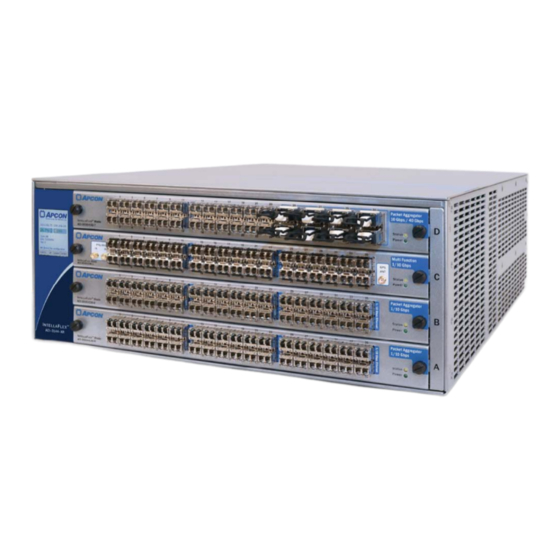
• Up to 36 ports on each blade (a maximum of 360 Gbps throughput per blade), with a total of 144 ports available (maximum of 1.44 Tbps throughput) The following illustration shows a front view of an ACI-3144-XR fully populated with APCON blades. Your chassis may have a different appearance if equipped with NTELLA different blades. - Page 16 Chapter 2. Introducing the chassis ACI-3144-XR Chassis User Manual APCON, Inc. A54-3144-XR • Rev B...
-
Page 17: Chapter 3: Specifications And Compatibility
This chapter describes the specifications for an APCON an I XR chassis. NTELLA Physical specifications This section describes the physical specifications for the ACI-3144-XR chassis. Size: Chassis Dimensions ACI-3144-XR 7.0 x 17.2 x 25.0 inches (17.8 x 43.7 x 63.5 cm) -
Page 18: Safety And Compliance
Customers must provide the source of power on site. Verify that there is enough power available to support all units that you plan to install in the rack. The ACI-3144-XR chassis operates with the following specifications for power requirements and consumption. These specifications assume that no blades are installed in the chassis. -
Page 19: Ac Power Specifications
ACI-3144-XR Chassis User Manual Chapter 3. Specifications and compatibility AC power specifications Following are the power specifications for the AC power supply in the ACI-3144-XR chassis: Power Supply Description • 1 00-240 volt AC , auto-sensing 50–60 Hz AC power supply •... -
Page 20: Dc Power Specifications
250 V A power cord for South Africa is also available (ACI-0080-550). Contact your sales representative for more information. DC power specifications Following are the power specifications for the DC power supply in the ACI-3144-XR chassis: Power Supply Description • DC power: —48 DC (–40 to –72 VDC) DC power supply •... -
Page 21: Dc Power Cords
Chapter 3. Specifications and compatibility DC Power Cords Each ACI-3144-XR chassis ships with one DC power cable (APCON P/N ACI-0080-600) with a pluggable terminal block for each DC power supply ordered. Following are the polarity specifications for the DC power supply. The orientation of the slots assumes that you are looking directly at the face of the power supply. -
Page 22: Dedicated Circuit Required
Chapter 3. Specifications and compatibility ACI-3144-XR Chassis User Manual Dedicated circuit required The circuit breaker panel must be equipped with a dedicated circuit for each –48V DC power supply installed in the chassis. Number of 30 Amp Number of power... -
Page 23: Specifications For Interfaces
ACI-3144-XR Chassis User Manual Chapter 3. Specifications and compatibility • Connect the chassis directly to the DC supply system earthing electrode conductor. The chassis may also be connected to a bonding jumper from an earthing terminal bar or bus to which the DC supply system earthed electrode conductor is connected. -
Page 24: Rj-45 Cable Pin-Outs
Chapter 3. Specifications and compatibility ACI-3144-XR Chassis User Manual RJ-45 cable pin-outs The RJ-45 modular cable includes the following pins: The pin-outs on the RJ-45 cable are as follows: Controller Terminal Signal Connection Signal Signal Input Output Input Output Input Output —... -
Page 25: Sd Card And Usb Port
ACI-3144-XR Chassis User Manual Chapter 3. Specifications and compatibility SD card and USB port The SD card and the USB slots on the controller panel are reserved for factory use only. Specialty interfaces Some blades may offer different connectors and interfaces on the front panel, such as those on either the ACI-3032-E36-1 Multi-Function blade, the ACI-3033-S14-1 II blade, or the ACI-3030-T05-1 Bypass TAP blade. -
Page 26: Compatibility
Chapter 3. Specifications and compatibility ACI-3144-XR Chassis User Manual Compatibility The following section describes the compatible blades and transceivers for an XR chassis. NTELLA Blades supported The following I blades are supported for use in an I XR chassis NTELLA NTELLA running current software. -
Page 27: Sfp Ports And Transceivers Supported
NOTE Transceivers shipped in APCON products are Class 1 laser products. Manufacturer specifications state that these transceivers comply with regulations and are certified to meet the Class 1 eye safety requirements of EN (IEC) 60825 and electrical safety requirements of EN (IEC) 60950. -
Page 28: Port Numbering
Chapter 3. Specifications and compatibility ACI-3144-XR Chassis User Manual Following are the characteristics for SFP+ and QSFP transceivers that can be ordered from APCON for an I XR chassis: NTELLA Transceiver Transmit power (nominal) Receiver sensitivity –11.0 dBm to –3.0 dBm –19.0 dBm @ 10.3 Gbps... -
Page 29: Chassis Defaults
ACI-3144-XR Chassis User Manual Chapter 3. Specifications and compatibility Chassis defaults Following are the default settings for an I XR chassis: NTELLA Setting Default Value IP address LAN 1 (default) 192.168.0.1 IP address LAN 2 Disabled; user-configurable Subnet mask LAN 1 (default) 255.255.255.0... - Page 30 Chapter 3. Specifications and compatibility ACI-3144-XR Chassis User Manual APCON, Inc. A54-3144-XR • Rev B...
-
Page 31: Chapter 4: Installation And Set Up
Connect power to the chassis 35 This chapter describes how to install and set up an I XR chassis. If you have any NTELLA questions during installation, please contact your sales office or APCON Technical Support as described in Contact APCON on page 10. -
Page 32: Safety Precautions
Chapter 4. Installation and set up ACI-3144-XR Chassis User Manual Safety precautions APCON recommends strict adherence to safety equipment measures defined by OSHA, 29 CFR Part 1910. Follow the precautions listed in this section when working with chassis and blades. -
Page 33: Unpack The Carton
2. Unpack the carton and inspect all components for damage. NOTE If any components appear damaged, contact APCON to obtain a Return Merchandise Authorization (RMA) number and further instructions. 3. Place components on a table or other surface near where you plan to install the chassis. -
Page 34: Install The Chassis
Rack installation Locate the rack and position where you plan to install the ACI-3144-XR chassis. Make sure that weight is balanced evenly in the rack after you install the chassis. Uneven weight distribution can result in a hazardous condition. -
Page 35: Install Blades And Transceivers
Chapter 6: Maintain the chassis on page 67. Connect power to the chassis You can order the ACI-3144-XR chassis with either AC or DC power supplies. See Power and electrical specifications on page 18 for the number of power supplies available and shipped as a minimum. -
Page 36: Connect Dc Power
Chapter 4. Installation and set up ACI-3144-XR Chassis User Manual ♦ To verify the operating status of each AC power supply. Check the two LED indicators: • The upper LED is green and indicates whether AC power is on or off. - Page 37 ACI-3144-XR Chassis User Manual Chapter 4. Installation and set up ♦ To prepare for a DC power connection: 1. Secure the conductors in compliance with strain relief regulations defined by your organization’s governing documentation and practices. 2. Complete power source termination according to standards defined by your organization’s governing documentation and practices.
-
Page 38: Connect The Chassis
Chapter 4. Installation and set up ACI-3144-XR Chassis User Manual Operating condition LED signal (continued) Lower LED (OUT or OK) Normal operation Solid green PSON High amber Blinking /OFF (1:1) Hot-Standby Mode Blinking amber green (1:2) V 1 or V SB out of regulation... -
Page 39: Chapter 5: Configure The Chassis
After you have set up the ACI-3144-XR chassis and applied power, change the default IP address to a number assigned for your network. By default, the ACI-3144-XR ships with its Active Controller LAN 1 management port set as follows: Identifier... -
Page 40: Use The Front Panel Interface
Chapter 5. Configure the chassis ACI-3144-XR Chassis User Manual Use the front panel interface The LCD touch screen located on the front panel of the chassis provides the fastest way to initially configure a chassis. Touching controls on the LCD screen displays menus where you can set configuration options and view status information. -
Page 41: Home Screen
ACI-3144-XR Chassis User Manual Chapter 5. Configure the chassis Home Screen The Home Screen is the first screen displayed after the chassis is powered. Information displayed on the Home Screen that is labeled in blue can later be changed by the user either in the W XR interface or by using CLI commands. -
Page 42: Status Menu
Chapter 5. Configure the chassis ACI-3144-XR Chassis User Manual Status Menu To access the Status Menu, press DOWN to scroll through the sub-menus on the Main Menu until the Status menu option is selected, then press ENTER. The Status Menu lists the following sub-menus:... -
Page 43: Status > Failover Status
ACI-3144-XR Chassis User Manual Chapter 5. Configure the chassis Component/Status Description (continued) No power supply is installed in this position. Temperature Indicates temperature and status. green Internal temperature is within specified limits. The Good ( default temperature’s maximum threshold is 80º C. -
Page 44: Status > Online Users
Chapter 5. Configure the chassis ACI-3144-XR Chassis User Manual This example shows that the Active Controller is installed in the primary slot, and the Standby Controller is installed in the secondary slot and in sync with the Active Controller. When viewing the LCD screen, be sure to note the slot for the Active Controller. Note that... -
Page 45: Configuration
ACI-3144-XR Chassis User Manual Chapter 5. Configure the chassis User names are truncated when displayed in the LCD screen. To view complete user names, use W XR (Global Settings toolbar > User Settings). Online Users Description Login Counters Displays how many users attempted to log into the switch. -
Page 46: Configuration > Audible Alarms
Chapter 5. Configure the chassis ACI-3144-XR Chassis User Manual Configuration > Audible Alarms To access the Audible Alarms menu, press DOWN to scroll through the sub-menus on Config Menu until the Audible Alarms menu option is selected, then press ENTER. The... - Page 47 ACI-3144-XR Chassis User Manual Chapter 5. Configure the chassis This screen lists sub-menus to set IPv4 parameters on the chassis. IPv4 Sub-menu Description IPv4 Enable Enables an IPv4 address for the chassis. LAN1 IPv4 Addr (see Sets the IPv4 address on the chassis to an available page 48 static IPv4 address on the network.
- Page 48 Chapter 5. Configure the chassis ACI-3144-XR Chassis User Manual Configuration > LAN IPv4 address The following steps describe how to set the IPv4 address for the LAN1 port on the chassis. These same instructions apply to the optional LAN2 port.
- Page 49 ACI-3144-XR Chassis User Manual Chapter 5. Configure the chassis 1. On the IPv4 Menu, press DOWN repeatedly until the LAN1 Netmask menu is selected, and then press ENTER. The following screen is displayed: 2. To set the desired netmask, use the...
-
Page 50: Configuration > Ipv6 Config
Chapter 5. Configure the chassis ACI-3144-XR Chassis User Manual 2. To set the desired gateway, use the CANCEL ENTER buttons to position the cursor over the first digit you want to change. • To move the cursor to the right, press ENTER. - Page 51 ACI-3144-XR Chassis User Manual Chapter 5. Configure the chassis IPv6 Sub-menu Description (continued) LAN2 IPv6 Addr (Optional) Sets the IPv6 address for the second LAN port on the chassis to an available static IPv6 address on your network. LAN2 Prefix (Optional) Sets the subnet prefix length for the second LAN port on the chassis.
- Page 52 Chapter 5. Configure the chassis ACI-3144-XR Chassis User Manual 5. Repeat the steps above until the desired IP address is displayed. 6. When the desired IP address is displayed, press ENTER to confirm.The chassis verifies the IP address and displays one of the following icons: The IP address is valid.
-
Page 53: Configuration > Telnet
ACI-3144-XR Chassis User Manual Chapter 5. Configure the chassis Configuration > LAN IPv6 gateway The following example sets the LAN1 IPv6 gateway on the chassis. 1. On the IPv6 Menu, press DOWN repeatedly until the LAN1 Gateway menu is selected, and then press ENTER. -
Page 54: Configuration > Ssh
Chapter 5. Configure the chassis ACI-3144-XR Chassis User Manual The Telnet menu determines Telnet availability. Option Description Enabled Users can access the switch over the network using CLI, APCON’s Telnet interface. Disabled (Default) CLI is not available over the network. User must use other methods to access the switch. -
Page 55: Configuration > Factory Reset
Configuration > Wipe Customers in high-security environments may find the Wipe function useful before passing the APCON chassis (or the Controller) to another department or to the factory (for example, to track an RMA return, trade, or upgrade). CAUTION Remember to first back up all switch settings and user data before deleting everything on the switch. -
Page 56: Failover
Chapter 5. Configure the chassis ACI-3144-XR Chassis User Manual To access the Wipe Memory? menu, press DOWN to scroll through the sub-menus on Config Menu until the Wipe menu is selected, then press ENTER. The following screen is displayed: The options include:... -
Page 57: Failover > Status
ACI-3144-XR Chassis User Manual Chapter 5. Configure the chassis Failover > Status For details about the Failover Status option, see Status > Failover Status on page 43 . NOTE This option does not apply to the ACI-3036-XR model, because that chassis has only one controller. -
Page 58: About
Chapter 5. Configure the chassis ACI-3144-XR Chassis User Manual About To access the Switch Information screen, press DOWN to scroll through the Main Menu. Highlight the About sub-menu, then press ENTER. The following screen is displayed: The following table describes the information listed on the Switch Information screen. -
Page 59: Use Web Xr To Configure The Switch
ACI-3144-XR Chassis User Manual Chapter 5. Configure the chassis Use W XR to configure the switch XR is a browser-based, graphical user interface embedded in the software that you can use to fully configure the chassis, view comprehensive status information, and make connections between ports. - Page 60 Chapter 5. Configure the chassis ACI-3144-XR Chassis User Manual 5. Access the host computer’s current network settings according to the instructions provided with the host’s operating system. Note the settings so that you can restore them at the end of this process. Temporarily change the host settings to the following: Host settings Change to …...
- Page 61 ACI-3144-XR Chassis User Manual Chapter 5. Configure the chassis 3. This displays the Global Settings toolbar. Click the soft arrow on the Global Settings icon and select Switch Settings. 4. On the Switch Settings page, click the LAN Interface tab.
-
Page 62: Name The Chassis (Optional)
Chapter 5. Configure the chassis ACI-3144-XR Chassis User Manual Step 3. Reconnect the host computer to your network Follow the steps below to reconnect the host computer. 1. Reset the host computer’s IP address, subnet mask, and gateway settings to their original values. - Page 63 ACI-3144-XR Chassis User Manual Chapter 5. Configure the chassis 2. From the pop-up menu, select Global Settings. 3. This displays the Global Settings toolbar. Click the soft arrow on the Global Settings icon and select Switch Settings. 4. On the Switch Settings page, click the Properties tab.
-
Page 64: Use Cli To Configure The Chassis
Chapter 5. Configure the chassis ACI-3144-XR Chassis User Manual Use CLI to configure the chassis Another option to configure the IP address is to use the embedded Command Line Interface (CLI). This interface provides commands for all configuration options and lets you view status and make connections. - Page 65 ACI-3144-XR Chassis User Manual Chapter 5. Configure the chassis 2. Connect the serial port on the chassis to the host computer’s COM port. ♦ Step 2. Establish communications and set the IP address 1. Start a communications program, such as HyperTerminal.
- Page 66 Chapter 5. Configure the chassis ACI-3144-XR Chassis User Manual The IP address command executes and the console banner again displays. This process may take several seconds. ♦ Step 3. Access the chassis using CLI After the IP address and netmask have been set, CLI may be accessed using either a Telnet or an SSH client.
- Page 67 Fan module 75 Software updates 82 System recovery 77 APCON chassis offer high availability designs with hot-swappable power supplies, blades, transceivers, and controllers that can be replaced while the chassis is powered. IMPORTANT As a system safeguard, it is strongly recommended that you first back up both configuration settings and user data before performing any maintenance tasks on the chassis or its components.
-
Page 68: Chapter 6: Maintain The Chassis
Replacement of controller battery The Controller in the chassis is equipped with a battery. However, the battery on all APCON controllers is not accessible and is therefore not a serviceable part. The battery cannot be replaced in the field, and you should not attempt to replace the battery. -
Page 69: Blades
ACI-3144-XR Chassis User Manual Chapter 6. Maintain the chassis Blades You can install a variety of blades in the ACI-3144-XR I XR chassis. For a list of NTELLA blades supported chassis, see page The slots for the blades are labeled alphabetically (A to B) on the right side of the chassis, starting with A in the lowest slot. -
Page 70: Transceivers And Fiber Optic Cables
Chapter 6. Maintain the chassis ACI-3144-XR Chassis User Manual ♦ To install a blade: 1. Hold the blade by its outer edges in front of the chassis. 2. Keeping the blade straight, slide it into chassis, using the guides on the inside edges of the chassis to align the blade properly. -
Page 71: Cleaning Tools
ACI-3144-XR Chassis User Manual Chapter 6. Maintain the chassis • Do not look into the end of an optical interface while the device is powered. The laser can cause harm to human eyes. • Add dust caps or covers to transceiver modules while cleaning (see page 74). - Page 72 Chapter 6. Maintain the chassis ACI-3144-XR Chassis User Manual 2. Cover connector ends and transceivers with clean dust caps when not in use, as shown here: Clean fiber optic cables You should always clean a cable before connecting it. • After every de-mating cycle, clean the ferrule before re-mating.
-
Page 73: Install And Remove Transceivers
ACI-3144-XR Chassis User Manual Chapter 6. Maintain the chassis Install and remove transceivers There are different types of transceiver modules used in the chassis. Some are equipped with a bale (or wire latch used to remove an SFP), and some with no bale and instead generally use a pull tab), as shown in the following examples: ♦... -
Page 74: Clean Transceiver Modules
Chapter 6. Maintain the chassis ACI-3144-XR Chassis User Manual Clean transceiver modules Here are some precautions to remember when cleaning transceiver modules: • Make sure you are in an area safe from ElectroStatic Discharge (ESD) and have taken appropriate precautions to eliminate static electricity when handling transceiver modules. -
Page 75: Fan Module
Fan module The ACI-3144-XR chassis contains a Fan Module. The number of fans on the tray for that Fan Module may vary, depending on the chassis; however, the entire Fan Module in any XR chassis is swapped at one time. -
Page 76: Controllers
4. Power up the chassis by connecting all power cords. Controllers The ACI-3144-XR chassis supports either one or two system controllers: a Primary Controller and Secondary Controller. Considerations when replacing a controller depend on whether a single controller or dual controllers are installed in the chassis:... -
Page 77: System Recovery
XR chassis. NTELLA 4. The controller is automatically powered up. System recovery If the system is in a locked state, please contact APCON Professional Services for technical assistance (see how to Contact APCON on page 10). Be prepared to provide details about hardware installed in the system, as well as the current version of software. -
Page 78: Before You Begin
Chapter 6. Maintain the chassis ACI-3144-XR Chassis User Manual Before you begin In this procedure, you will remove and reinstall controllers, as well as remove and replace power cables to turn power off and on again. ESD CAUTION To avoid damage to hardware from ElectroStatic Discharge (ESD), do not touch devices without first taking appropriate precautions. - Page 79 ACI-3144-XR Chassis User Manual Chapter 6. Maintain the chassis 2. From the pop-up menu, select Global Settings. 3. This displays the Global Settings toolbar. Click the soft arrow on the Global Settings icon and select Switch Settings. 4. Click the tab for the LAN Interface.
-
Page 80: Power Down The Chassis
Chapter 6. Maintain the chassis ACI-3144-XR Chassis User Manual The slider turns OFF and the status is updated: 7. Remove the Standby Controller in the upper slot. For instructions, see Remove the Secondary Controller on page 78. Power down the chassis It is recommended that you regularly back up all system settings and user data. -
Page 81: Reset The Secondary Controller
ACI-3144-XR Chassis User Manual Chapter 6. Maintain the chassis ♦ To reset the Primary Controller: 1. Gently insert the straightened paper clip into the pinhole on the Primary Controller, which is the controller in the lower slot on the back of the chassis. -
Page 82: Log Into Web Xr And Restore Settings
Chapter 6. Maintain the chassis ACI-3144-XR Chassis User Manual 3. Using the extended paper clip, press and hold the pinhole reset button on the Secondary Controller. 4. Continue to press and hold the extended paper clip into the pinhole reset button until the status LED lights stop flashing. - Page 83 ACI-3144-XR Chassis User Manual Chapter 6. Maintain the chassis APCON makes a best effort to test with all releases of software to ensure compatibility. However, the time to upgrade may be greater than expected, since features change significantly with each release and new hardware may be introduced.
- Page 84 Chapter 6. Maintain the chassis ACI-3144-XR Chassis User Manual APCON, Inc. A54-3144-XR • Rev B...
-
Page 85: Index
LED email and telephone ESD Caution Mobile app green software operational status of SFP Support Site and website technical support compatibility APCON Mobile App blades audible alarms transceivers transceivers supported compliance battery, do not remove Configuration Menu blades configure... - Page 86 Index ACI-3144-XR Chassis User Manual conventions in manual LCD switch information screen set using W label types Google Chrome notifications Customer Support tunnel green AC power supply status DC power supply DC power supply status dedicated circuit required LCD touch screen...
- Page 87 ACI-3144-XR Chassis User Manual Index IP address Microsoft Internet Explorer configure on touch screen minimum requirements configuring using CLI web browsers configuring using the front panel LCD Mobile App monitor switches configuring using W Mozilla Firefox requirements using WebXR name of switch...
- Page 88 Index ACI-3144-XR Chassis User Manual QSFP+ transceivers interfaces physical power and electrical safety and compliance receive signal (RX) switch defaults receiver sensitivity LCD touchscreen status indicators regulatory compliance Subnet mask remove Support Site blade supported blades controller switch fan module...
- Page 89 ACI-3144-XR Chassis User Manual Index transceivers supported transmit power transmit signal (TX) troubleshooting transceivers TX signal unpack the carton user manual, contents user-selectable rates ventilation slots web browser Chrome Firefox Internet Explorer web browsers supported website for APCON XR software...
- Page 90 Index ACI-3144-XR Chassis User Manual APCON, Inc. A54-3144-XR • Rev B...
Need help?
Do you have a question about the ACI-3144-XR and is the answer not in the manual?
Questions and answers