
Related Manuals for Warner Electric MCS2000-PSDRV2

Summary of Contents for Warner Electric MCS2000-PSDRV2
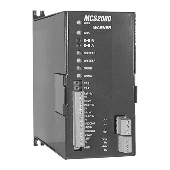
- Page 1 MCS2000-PSDRV2 Power Supply/Dual Voltage/Dual Channel Driver Installation & Operating Instructions 819-0525 P-2010-7...
-
Page 2: Table Of Contents
Listing of figures and illustrations ...21 MCS2000-PSDRV2 without having to make any Warranty Information ....BC mechanical changes in the mounting footprint. -
Page 3: Specifications
Specifications Model: MCS2000-PSDRV2 Dual Channel/Dual Status and Diagnostic Indicators: 2 LED’s on Voltage Driver each channel indicate normal operation and fault conditions during operation. One Green and one Part Number: 6910-448-110 Red LED. Power Supply Section: Protection Input: Polarity protected to prevent damage in the event of inversion of DC power Input: 100 –... -
Page 4: Installation
Using either 4.5 mm or #10 screws, mount proceeding to the wiring section. the unit to the panel or mounting surface. Tighten screws sufficiently so that unit will Driver Outline and Mounting Dimensions Figure 1 Mounting Dimensions Warner Electric • 800-825-9050 P-2010-7 • 819-0525... -
Page 5: System Wiring
If only a single brake is to be used on the The MCS2000-PSDRV2 will operate with any of MCS2000-PSDRV2, then skip to either the 24 volt the MCS2000 series Controllers. It will provide brake wiring section, page 8 or the 48 Volt brake interface between the brakes and the MCS2000- wiring section, page 10. - Page 6 MCS2000-PSDRV2 Driver MCS2000-ECA Controller Note: Wiring is shown for both channels. If only one channel is required, then follow wiring for channel “A”. Figure 2 MCS2000-EC to MCS2000-PSDRV2 Wiring to the MCS2000-CT’S Controllers Note: Since the MCS2000-CTDA and MCS2000-CTLC controllers have 25 pin DB connectors with cables wiring is made via the cable.
- Page 7 MCS2000-CT controller to terminal 1 In A MCS2000-CT controller to terminal 0 – 10 V on the MCS2000-PSDRV2. 3 In B 0-10 V on the MCS2000-PSDRV2. Insure that the terminal on the Insure that the terminal on the MCS2000-PSDRV2 is tightened securely.
-
Page 8: Volt Brake Systems
Wire the negative side (-) or DC common terminals 7 and 8 on the MCS2000- of the 24 volt DC power supply to terminal PSDRV2. Make sure the terminals are 9 of the MCS2000-PSDRV2. Make sure securely tightened. the terminal is securely tightened on the MCS2000-PSDRV2. - Page 9 Wire the negative side (-) or DC common sure the terminals are securely tightened. of the 48 volt DC power supply to terminal 9 of the MCS2000-PSDRV2. Make sure the terminal is securely tightened on the MCS2000-PSDRV2. Warner Electric • 800-825-9050...
-
Page 10: Volt Brake Systems
Note: Warner Electric Tension brakes are not - designations. polarity sensitive, so wiring between The following 24 volt tension brakes can be terminals on the MCS2000-DRV2 and used with the MCS2000-DRV2 Driver for 48 volt brake are not sensitive to the + and operation with overcurrent feature. -
Page 11: System Start-Up
Tension Control and Driver, the Channel “A” brake on terminals Driver and Brake or Brakes, and 24 Volt 5 and 6 of the MCS2000-PSDRV2. Power Source and Driver. Terminal 5 is positive, and terminal 6 is negative. Note that the o 2. - Page 12 Voltage can be measured to the Channel “B” anti-residual. the Channel “B” brake on terminals Proceed to step 6. 7 and 8 of the MCS2000-PSDRV2. Terminal 7 is positive, and terminal 8 is negative. Note that the “GREEN” LED for Channel “B” is The Channel “B”...
- Page 13 “A” fully counter-clockwise so the output voltage to the brake is zero level. Voltage can be measured to the Channel “A” brake on terminals 5 and 6 of the MCS2000-PSDRV2. Warner Electric • 800-825-9050 P-2010-7 • 819-0525...
- Page 14 Voltage can be measured to the Channel “B” brake on terminals 7 o 5a. Using a digital DC Voltmeter, and 8 of the MCS2000-PSDRV2. connect the positive lead to terminal Terminal 7 is positive, and terminal 8 3 and the negative lead to terminal is negative.
- Page 15 20 hertz, brake is operating in the overcurrent with the “ON” time of approximately mode and will be limited to 60 0.5 second and the “OFF” time of seconds. approximately 2.5 seconds. The Warner Electric • 800-825-9050 P-2010-7 • 819-0525...
- Page 16 9b. Allow the control to operate in this o 12. This completes the set up of the mode for 60 seconds or more and MCS2000-DRV2 Driver. observe the LED’s. After the Warner Electric • 800-825-9050 P-2010-7 • 819-0525...
-
Page 17: System Troubleshooting
There are certain basic checks that can the driver and void the warranty. be made using a digital meter. All readings taken on the MCS2000-PSDRV2 will be either DC The following diagnostic indications are possible voltages or DC currents, or AC line voltage. A with the two indicator LED’s on the face of the... - Page 18 Green Green Internal installation error at power up. Fault Error. Output locked “OFF”, Driver has tripped. Return MCS2000-PSDRV2 for Repair. Short Circuit or Overload on Output at Power Up. Output Locked “OFF”, Driver 1.5 Sec ON/0.5 Sec OFF has tripped.
- Page 19 Check LED’s for various conditions. Check incoming DC power to MCS2000-PSDRV2 either 24 VDC or 48 VDC. Check that power is applied. If unit has power, check that input signals to Input “A” and Input “B” vary between 0 and 10 VDC.
- Page 20 Warner Electric Representative or Warner Electric Distributor should be contacted for additional assistance. This completes the installation of the MCS2000-PSDRV2 Driver. This manual covers only the Driver and does not cover the controller part of the system. Refer to the appropriate manual for set-up and operation of the controller.
-
Page 21: Listing Of Figures And Illustrations
Figure 4 24 Volt Power and Brake Wiring Figure 5 48 Volt Power and Brake Wiring LED Indicator Operations and Figure 6 Descriptions – Normal LED Indicator Operations and Figure 7 Descriptions – Faults Warner Electric • 800-825-9050 P-2010-7 • 819-0525... -
Page 22: Warranty Information
Warner Electric LLC’s obligation under this warranty is limited to the repair or replacement of the defective product and in no event shall Warner Electric LLC be liable for consequential, indirect, or incidental damages of any kind incurred by reason of the manufacture, sale or use of any defective product.
Need help?
Do you have a question about the MCS2000-PSDRV2 and is the answer not in the manual?
Questions and answers