Table of Contents
Advertisement
Quick Links
Advertisement
Table of Contents
Troubleshooting

Summary of Contents for Hydrim L110W
- Page 1 Hydrim L110W Training Manual Training Manual...
-
Page 2: Table Of Contents
Programming for HIP Cleaning Solution Revision 2.02 Software Water Test Kit Preventative Maintenance Kit Preventative Maintenance Kit Installation 29-34 Draining the Hydrim L110W for Shipping Parts Front View Door Closed Parts Front View Door Open Parts Left Side No Cover Parts Right Side No Cover Parts Water Inlet Valve, Inlet Temp Sensor &... -
Page 3: Description & Cycle Times
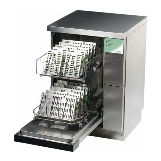
Description & Cycle Times The Hydrim L110W Instrument Washer is designed to help you achieve an exceptional level of cleanliness while providing a simplified method of washing dental instruments. There is no need to pre-soak items but cement and composites still need to be removed from instruments. Note: Burs and handpieces should not be placed in the Hydrim. -
Page 5: Quick Reference Guide
Note: Rinse Aid is not required when using HIP solution with revision 2.02 software. See Checking & Programming Control Module to check software revision. -
Page 6: Installation
Installation Cold Water Hot Water Water, Drain & Power Connections The unit is supplied with two water intake hoses, which are 6.5 ft. long, and they connect to ¾ “ garden hose fittings. The unit is supplied with a 5ft. flexible drain hose with an inner diameter of ¾”. It should be connected to a drain point no more than 14”... -
Page 7: Water Flow & Backflow Protection
Water Flow & Backflow Protection Water Inlet When the hot or cold-water inlet valve is open, the water flows to Water Inlet Channel 1 of the Sidebag. From there it flows up to the Air Gap. The Air Gap 3 is between Channel 1 and 2. The water under pressure shoots over the Air Gap. -
Page 8: Sequence Of Operation P0 Cycle Revision 2.02 Software
Hydrim L110W P0 Cycle with Revision 2.02 Software Preparation drain pump runs When the P0 cycle button is pressed the drain pump turns ON. The Hydrim will drain the wash chamber and the sidebag. If the previous cycle was interrupted when the cycle is started the drain pump will run for 80 seconds. - Page 9 Hydrim L110W P0 Cycle with Revision 2.02 Software (Cond.) Circulation Circulation pump M1 remains ON for 60 seconds/1 minute. Circulation and evacuation 10 seconds Circulation pump M1 remains ON. Turn ON drain pump M2. Evacuation 20 seconds Circulation pump M1 turns OFF. Drain pump M2 remains ON for 20 seconds.
-
Page 10: Sequence Of Operation P1 & P2 Cycle Revision 2.02 Software
Hydrim L110W P1 & P2 Cycle with Revision 2.02 Software Preparation drain pump runs When the P1 or P2 cycle button is pressed the drain pump turns ON. The Hydrim will drain the wash chamber and the sidebag. If the previous cycle was interrupted when the cycle is started the drain pump will run for 80 seconds. - Page 11 Dosing pump runs for 5 seconds. If flow switch does not detect dosing before the dosing error timer ends (30 seconds), the Hydrim fails with an ED code. Once selected dosing time is achieved the dosing pump will turn OFF.
-
Page 12: Sequence Of Operation P3 & P4 Cycle Revision 2.02 Software
Hydrim L110W P3 & P4 Cycle with Revision 2.02 Software Preparation drain pump runs When the P3 or P4 cycle button is pressed the drain pump turns ON. The Hydrim will drain the wash chamber and the sidebag. If the previous cycle was interrupted when the cycle is started the drain pump will run for 80 seconds. - Page 13 Dosing pump runs for 7 seconds. If flow switch does not detect dosing before the dosing error timer ends (30 seconds), the Hydrim fails with an ED code. Once selected dosing time is achieved the dosing pump will turn OFF.
- Page 14 Dosing pump runs for 5 seconds. If flow switch does not detect dosing before the dosing error timer ends (30 seconds), the Hydrim fails with an ED code. Once selected dosing time is achieved the dosing pump will turn OFF.
-
Page 15: Control Panel & Fault Codes
Control Panel Power Switch Display Door Handle Check software revision: With unit OFF hold in buttons P3 & P4 turn the unit ON and release all buttons. The display shows “r” in the first digit followed by the first digit of the revision number and then the last two digits. -
Page 16: Troubleshooting E1 Error Codes
Error Code 1 indicates water temperature is below a set point after timeout during heating phase of the cycle. 1. Remove hot water inlet hose and check for hot water to Hydrim. 2. Check inlet filter screen is clean on hot water valve. -
Page 17: Troubleshooting E2 Error Codes
Troubleshooting E2 Error Code Error Code E2 indicates a timeout before the chamber is filled with water. 1. Remove left and right side covers from unit. 2. Check flow switch on right side of unit. If cleaning solution is leaking around wires of flow switch disconnect flow switch wires and start a P0 cycle. -
Page 18: Troubleshooting E4 Error Codes
Troubleshooting E4 Error Code Error Code 4 indicates failure of water evacuation from chamber before 60-second timeout. 1. If the chamber is empty remove the filters from inside the chamber and pour some water into the base of the chamber. Turn the unit ON and select P0. The drain pump should turn ON and evacuate the water from the chamber. -
Page 19: Troubleshooting Ed & Ef Error Codes & Chemical Light On Steady
Hydrim L110W Troubleshooting ED & EF Error Codes Error code ED indicates a dosing system failure. 1. Check cleaning solution box for solution and check for a kinked tubing. 2. Remove the right side cover. 3. Disconnect tubing connected to suction side of dosing pump. Verify that cleaning solution is flowing to the dosing pump. -
Page 20: Flow Switch Configurations & Dryer Check Valve Location
Flow Switch Configurations & Dryer Check Valve Location Original Flow Switch Black Flow Switch Flow Switch Flow Switch Hose Clamps Black Flow Switch with Mounting Bracket Dryer Check Valve Flow Switch Check Valve... -
Page 21: Master Controller Replacement
Master Controller Replacement Remove six Torx 20 screws from inside top of door. There are four screws across the top, one coming in from the left side and one coming in from the right side. Disconnect red, white & blue wires from 3 pin terminal strip on right side of controller. Remove all plugs from controller &... -
Page 22: Slave Controller Replacement
Slave Controller Replacement Remove the top cover (see cover removal). Open the cleaning solution drawer. Remove the 7mm hex screw holding the top of the panel above the solution drawer. This screw is accessible with top cover removed from inside unit. Slide a flat screwdriver under the top panel and pry it loose. -
Page 23: Master Controller Wiring Diagram & Picture
Master Controller Wiring Diagram Y1-Cold Water Valve B1-Chamber Full Pressure Switch Y2-Salt (Regeneration Valve) B2-Chamber Overflow Switch Y6-Drain Valve for Sidebag B8-Pressure Switch for Heater Y7-Hot Water Valve B10-Temperature Cutoff Switch for Heater Y8-Rinse Aid Actuator B11-Low Salt Switch M1-Circulation Pump B12-Low Rinse Aid Switch M2-Drain Pump B15-Chemical Flow Switch... -
Page 24: Slave Controller Wiring Diagram & Picture
Slave Controller Wiring Diagram M3-Dryer Motor B6-Not Used T1-Chamber Temperature Sensor M4-Dosing Pump 1 B7-Not Used ER-External Relay M5-Not Used X6-Jumpered C-External Capacitor Slave Controller Wiring Picture X5 Pins 1-7 X4 Pins 1-8... -
Page 25: Checking & Programming Control Module
Checking & Programming Control Module By pressing various combinations of buttons, it is possible to enter special cycles. To use these cycles, hold the two buttons indicated and power the unit on. 1. “regeneration (salt) level set”: By pressing buttons P1 & P2 while powering the unit on the display shows “L”... -
Page 26: Programming For Hip Cleaning Solution Revision 2.02 Software
(For example if the revision is 2.02 then the display will show r2 followed by 02). If the Hydrim L110W has 2.02 software proceed with the programming. The Hydrim L110W software has been upgraded for use of the HIP (Hydrim Instrument Protection) Cleaning Solution. -
Page 27: Water Test Kit
The Water Test Kit is used to test the hardness of the water. If the reading is above 180 ppm softening salts may be required in the Hydrim. To test the water, go to a sink close to the Hydrim. Remove one of the three test strip packets from the envelope. -
Page 28: Preventative Maintenance Kit
Preventative Maintenance Kit Part #01-109707S Item # Description Inlet tubing’s for hot and cold water Tubing assembly with sensor from inlet valve block to sidebag Water inlet valve block Vent tubing for top of sidebag Tubing’s from flow switch to dosing pump and dosing pump to chamber Flow switch Flow switch mounting bracket Wiring harness for new valve block... -
Page 29: Preventative Maintenance Kit Installation
Hydrim L110W Preventative Maintenance Kit Installation Procedure Remove All Covers Removing the Top Cover Using a flat screwdriver, release the latch located at the back right of the unit. Pull the cover back about ½”. Lift the cover off. Removing the Back Cover Remove the screws in each corner of the panel. - Page 30 Old Hot/Cold Inlet Valve Removal Disconnected inlet valve tubing under left side panel. Remove four hex head screws holding inlet valve plate using 7mm nut driver in rear of unit. Inlet Valve Tubing Inlet Valve Plate Remove hot/cold inlet valve block assembly with tubing from back of unit. Disconnect wires to valves.
- Page 31 Installing Hose Assembly with Temperature Sensor Hose Assembly with Temperature Sensor Feed the temperature sensor wire and plug into existing connector. Push the temperature sensor down as shown Guide the black tubing towards the hot & cold valve location. Push the assembly in so wires and hose are Connect new temperature sensor to plug accessible where valve block was removed.
- Page 32 Installing New Hot/Cold Inlet Valve Wiring connections old valve block New hot/cold valve block wiring harness Hot water connection Neutral Cold water connection Cold water 1 Neutral 2 Hot water 1 connection purple wire purple wires gray wire Cut purple and gray wires from old valve block New valve block terminals wiring harness and connect to new harness.
- Page 33 Connect valve plate by connecting 2 center screws first, then 3 corner screws using 8mm nut driver. Screws are self-tapping and corner screws need to thread into the plastic. Center Screws Removal and Installation of Flow Switch Assembly with Tubing Remove the old flow switch and tubing going to Attach new flow switch wires to terminal block dosing pump and chamber.
- Page 34 Connect new tubing from dosing pump to chamber and secure with a cable tie. Hose to chamber Sidebag Vent Tubing Installation Trim sharp edge with knife as shown below Sidebag Vent Hole Secure the tubing with a cable tie to the top of the insulation by piercing two holes into the insulation and routing the tie through the holes to hold the tube.
-
Page 35: Draining The Hydrim L110W For Shipping
Draining the Hydrim L110W for Shipping 1. To empty the sidebag: • Start P1 cycle • Interrupt cycle at the filling stage • Disconnect hot and cold water connection • Restart the cycle for 1 min. • Observe the side bag is empty 2. -
Page 36: Parts Front View Door Closed
Parts Front View Door Closed Item # Part# Description 50750.10 Cover Top 13790.06 Decals (Set of 2) 13459.00 Power Switch 13471.01 Button ON/OFF Silver 16945.00 Door Lock Handle 16979.02 Cover Door Front 16648.01 Kick Plate Front 16695.00 Cover Right Side 16662.06 Cover Cleaning Solution Drawer 16663.06... -
Page 37: Parts Front View Door Open
Parts Front View Door Open Item # Part# Description 13492.00 Wash Arm Upper 13456.00 Door Gasket 13638.00 Lid Salt Container 13481.00 Wash Arm Lower 13611.06 Door Inner Panel 13466.00 Filter Bottom Flat 13465.00 Filter Bottom Round 13629.00 Pipe Water Feed to Wash Arm... -
Page 38: Parts Left Side No Cover
Parts Left Side No Cover Item # Part# Description 13462.00 Sidebag 13455.00 Drain Tubing 13614.00 Solenoid Valve Drain 13615.00 Solenoid Valve Regeneration 13447.01 Emitter Housing Red 13447.00 Emitter Housing Clear... -
Page 39: Parts Right Side No Cover
Parts Right Side No Cover Item # Part # Description 13319.10 Dryer Air Filter 18466.00 Dryer Air Turbine 13416.01 Check Valve Dryer 1” 01-111474S Flow Switch 13599.00 Foot Front 21624.02 Dosing Pump Clamp External 13634.00 Dosing Pump 21027.00 Tubing Exhaust Air... -
Page 40: Parts Water Inlet Valve, Inlet Temp Sensor & Controllers
Parts Water Inlet Valve, Inlet Temp Sensor & Controllers New Inlet Valve Old Inlet Valves Note: If Water Inlet Valve is defective install Preventative Maintenance Kit #01-109707S or Inlet Valve, Wiring Harness & Temp Sensor Kit #01-109863S. Temp Sensor Item # Part# Description 16945.00... -
Page 41: Hydrim L110W Preventative Maintenance Kit
Preventative Maintenance Kit Part #01-109707S Item # Description Inlet tubing’s for hot and cold water Tubing assembly with sensor from inlet valve block to sidebag Water inlet valve block Vent tubing for top of sidebag Tubing’s from flow switch to dosing pump and dosing pump to chamber Flow switch Flow switch mounting bracket Wiring harness for new valve block...
Need help?
Do you have a question about the L110W and is the answer not in the manual?
Questions and answers