
Related Manuals for Dynapac LT6000

Summary of Contents for Dynapac LT6000
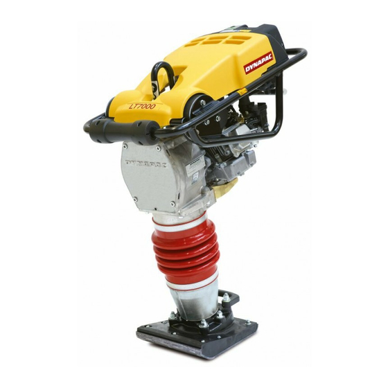
- Page 1 DYNAPAC Rammer WORKSHOP MANUAL LT6000/7000 WLT6000-1EN1 Box 504, SE-371 23 Karlskrona, Sweden Phone: +46 455 30 60 00, Fax: +46 455 30 60 30 www.dynapac.com...
- Page 3 Vibrating Rammer LT 6000/7000 Workshop Manual WLT6000-1EN1 This workshop is valid from SN: LT6000 PIN (S/N) *76100020* LT7000 PIN (S/N) *77100020* Published workshop issues valid for these tampers: Work shop Issue date WLT6000 - 1EN1 2003 - 01 We reserve the right to change specifications without notice.
-
Page 4: Table Of Contents
Reassembly the engine (LT6000/7000) ......5 Disassembly and reassymbly the clutch ......6 Exchange the centrifugal clutch ........6 General view for the clutch, LT6000/7000....... 6 Carburetor LT 6000 ............7 Carburetor LT 7000 ............7 Recoil starter, honda ............8 Recoil starter, honda ............ -
Page 5: Technical Specifications
TECHNICAL SPECIFICATIONS Model Engine Idling revs/ Fueltank Engine oil Rammer leg Operating lit. (qts) lit. (qts) lit. (qts) speed LT 6000 Honda GX 100 1550/3600 2,5 (2,65) 0,3 (0,32) 0,9 (0,95) LT 7000 Honda GX 120 1400/3600 2,5 (2,65) 0,4 (0,42) 0,9 (0.95) OIL SPECIFICATIONS Engine oil... -
Page 6: Tools
TOOLS General information: Alwys use plastic hammer when disassembly or reas- sembly parts. SIGN PLATE The sign plate is mounted on the left side of the housing. Always state Serial Number before ordering new parts from the Spare Parts Catalogue. W000049A WLT6000-1EN1... -
Page 7: Disassembly The Engine (Lt6000/7000)
DISASSEMBLY THE ENGINE (LT6000/7000) Separating the engine from the gear housing 1. Close the fuel valve on the tank. 2. Remove the throttle lever from the handle. 3. Remove the fuel hose from the tank. 4. Remove engine support (4) (only on LT 7000). -
Page 8: Disassembly And Reassymbly The Clutch
3. Remove the washer (3) and the clutch (4). In some case it is necessarily to use a puller to loosen the clutch. The washer (3) is not valid for LT6000 4. Mount the new clutch and torque 60 Nm. -
Page 9: Carburetor Lt 6000
CARBURETOR LT 6000 Adjustment of carburetor LT 6000 The air cleaner must be clean before making any adjustment. The engine must be warm before adjusting the speed. Revs: Idling revs 1550 ± 150 v/min Engagement revs of centrifugal clutch about 2500 rpm Operating speed about 3750 rpm Idle speed adjustment... -
Page 10: Recoil Starter, Honda
RECOIL STARTER, HONDA 1. Insert the hook (1) on the outer side of the spring into the groove (2) inside the reel. W000009A Fig. 7 Recoil starter 1. Hook 2. Groove 2. Pass the starter rope through the starter reel and tie (1) it as shown. -
Page 11: Recoil Starter, Honda
RECOIL STARTER, HONDA 5. Pass the starter rope end through the starter case rope guide and pull it outwards. Pass the starter rope though the starter grip and tie the rope as shown. Do not separate the starter reel from the starter case. -
Page 12: Valve Clearance Lt 6000
VALVE CLEARANCE LT 6000 Valve clearance inspection and adjustment must be performed with the engine cold. 1. Loosen the four 6 x14 mm flange bolts(1). W000016A Fig. 14 Valve. 1. Flange bolts x4 2. Cylinder head cover 2. To remove the head cover, insert a screw driver or equivalent tool into the recess in the position of cylinder shown. -
Page 13: Valve Clearance Lt 6000
VALVE CLEARANCE LT 6000 5. Insert the feeler gauge (1) between the valve adjusting screw and the valve and measure the valve clearence. 0,15 ± 0,02 mm (0,006 ± 0,001 in) Standard valve clearance 0,20 ± 0,02 mm (0,008 ± 0,001 in) W000019A Fig. -
Page 14: Valve Clearance Lt 7000
VALVE CLEARANCE LT 7000 Valve clearance inspection and adjustment must be performed with the engine cold. 1. Remove the four cylinder bolts, cylinder head cover and gasket. W000021A Fig. 19 Valve 1. Bolts 2. Cylinder head cover 3. Gasket 2. Set the piston at top dead center of the compression stroke (both valves fully closed). -
Page 15: Disassembly The Bellow
DISASSEMBLY THE BELLOW Changing the bellows 1. Remove the engine from gear house (see page 4). 2. Loosen the four screws crosswise (7). 3. Turn the clutch (2) so the crankshaft (3) comes in it`s outermost position. Lift up crankcase and press down outer tube (4). -
Page 16: Reassembly The Bellow
REASSEMBLY THE BELLOW Changing the bellows 1. Clean surfaces between bellow (1), bellow support (2) and outer tube (3) 2. Change the bellows. 3. Refit the outer tube. 4. Align the machine and tighten the hose clamps (6). Opposite directions for the hose clamps (6). 5. -
Page 17: Disassembly The Crank Case
DISASSEMBLY THE CRANK CASE 1. Remove the crank case. (see previous side). 2. Unscrew the four screws crosswise (1) and remove the cover unit (2). W000042A Fig. 27 Crankcase 1. Screw x4 2. Cover 3. Remove the snap ring (3) and remove the crank shaft. -
Page 18: Diassembly The Crank Case
DIASSEMBLY THE CRANK CASE 7. Dismantle of pinion (10). Remove snap ring (11) as holding pinion. Remove pinion shaft from gear housing by hitting the pinion shaft from the gear side using a steel bar and a plastic hammer. W000045A Fig. -
Page 19: Reassembly The Crank Case
REASSEMBLY THE CRANK CASE 1. Before reassemblying the crank case, clean parts and surfaces. Check the O-ring so it is in good conditions. Before reassembly the bearing (1) don't forget the snap ring (2) Mount the bearing (1) and the snap ring (3) Mount the snap ring (2) in the cover unit W000043A Fig. -
Page 20: Spring Unit
SPRING UNIT Dismantling the spring assembly 1. Dismantling is the same as change of bellows. 2. Remove rod piston head (1).Use an open end spanner (size 23) to hold the piston shaft 3. Drain the oil from spring cylinder assy before turning it upside down. -
Page 21: Foot
FOOT Replacing the complete foot 1. Unscrew the six (1) M12 nuts holding the foot to the bellows bracket. 2. Replace the old foot with a new one. 3. Reassemble and torque with 78 Nm. Replacing the "bottom" steel plate 1. - Page 22 Box 504, SE-371 23 Karlskrona, Sweden Phone: +46 455 30 60 00 Fax: +46 455 30 60 30 www.dynapac.com...
Need help?
Do you have a question about the LT6000 and is the answer not in the manual?
Questions and answers