Table of Contents
Advertisement
Advertisement
Table of Contents

Related Manuals for Park Air Systems 6525

Summary of Contents for Park Air Systems 6525
- Page 1 Draft 6525 Multimode Digital Radio User Documentation...
- Page 2 When logged on, select the public (Pub) folder, then the Handbook Errata Sheets folder, and then select the required equipment model. [Adobe Acrobat™ must be loaded on your PC to use this facility] Handbook Title: 6525 Multimode Digital Radio User Documentation Handbook Part Number: 31-3MDR00HB Handbook Version:...
- Page 3 Draft Health and Safety Warnings A warning is used to indicate possible danger to personnel. Throughout Park Air handbooks, warnings are indicated by the following symbols: WARNING Indicates electrical danger to personnel. Indicates a hazardous material. WARNING WARNING Indicates a non-ionizing radiation hazard. WARNING Indicates a specified danger to personnel.
-
Page 4: Mdr00Hb
Draft Health and Safety (Continued) Specific Warnings Applicable to the MDR WARNING Dangerous Voltage The instructions given in this documentation involve connecting dangerous voltage to the MDR. Installation must be carried out only by suitably qualified personnel. WARNING Earth Connection This equipment must be earthed. - Page 5 Draft Disposal This product is covered by the European Directive 2002/96/EC. It must not be disposed of in domestic waste. Disposal should be made using designated collection facilities appointed by the government or local authority in your area. 31-3MDR00HB Page 5...
- Page 6 Draft List of Abbreviations alternating current ACARS aircraft communications, addressing and reporting system amplitude modulation built-in test celsius decibel power ratio in decibel (dB) referenced to one milliwatt (mW) direct current electrostatic sensitive devices figure hertz kilogramme kilohertz liquid crystal display metre milliamp multimode digital radio...
- Page 7 Draft Approvals and Standards 6525 Multimode Digital Radio The equipment is designed to meet the following requirements: RoHS Directive 2002/95/EC WEEE Directive 2002/96/EC ICAO Annex 10 Vol lll Part 1 Chapter 6 EN 301 841-1 Electromagnetic compatibility and Radio spectrum Matters (ERM); VHF air-ground Digital Link (VDL) Mode 2;...
- Page 8 Draft Intentionally Blank 31-3MDR00HB Page 8...
-
Page 9: Table Of Contents
Draft Contents Page Overview Introduction Operating Modes MDR Applications Hardware Configuration Software Configuration Specification MDR Operating Characteristics Dimensions and Weight Input Supply Requirement Environmental Operation Controls and Indicators Introduction Controls and Indicators Ready Indicator Alarm Indicator Receive Indicator Transmit Indicator Scroll/Select Switch and LCD Connectors Reference Connector... - Page 10 Draft Contents (continued) Page Maintenance Maintenance Policy Unscheduled Maintenance Scheduled Maintenance Cleaning the Equipment Security of External Connections Checking the MDR’s Internal Reference Frequency Initiating an Interruptive BIT Test Removing and Refitting the Cooling Fan 31-3MDR00HB Page 10...
-
Page 11: Overview
Draft Overview... -
Page 12: Introduction
Fig 1 6525 Multimode Digital Radio (MDR) Operating Modes Operating modes are software controlled. A 6525 MDR can be loaded with any two of the four available software fills shown in Fig 2. All four software fills are available to download through the user’s network. -
Page 13: Mdr Applications
VDL mode 2 is a higher bandwidth, connection orientated service, operating at 31.5 kbits per second using D8PSK modulation. Hardware Configuration The product model is: 6525 MDR. The part number is: B6525. A hardware configuration label is fixed to the MDR’s rear panel. The label shows the model, part number, serial number and modification status. - Page 14 Intentionally Blank...
-
Page 15: Specification
Draft Specification... -
Page 16: Mdr Operating Characteristics
Draft MDR Operating Characteristics Frequency range Between 118 and 136.975 MHz Number of channels Channel spacing 25 kHz (all modes) 8.33 kHz (Am-Voice mode only) Modulation modes ACARS 13K0A2D VDL Mode 2 14K0G1D AM-Voice (25 kHz) 6K00A3E AM-Voice (8.33 kHz) 5K00A3E Frequency stability Better than 1 ppm within permissible environmental conditions Dimensions and Weight... -
Page 17: Operation
Draft Operation... -
Page 18: Controls And Indicators
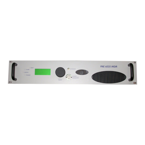
Draft Controls and Indicators Introduction This topic describes the MDR’s front panel (see Fig 5) controls, indicators and connectors. Fig 5 MDR Front Panel Controls and Indicators Ready Indicator A green indicator that lights when the MDR is ready for use and no BIT faults have been detected. Alarm Indicator A red indicator that either flashes, or lights, when a BIT fault has been detected. -
Page 19: Scroll/Select Switch And Lcd
Draft Scroll/Select Switch and LCD The Scroll/Select switch is used in conjunction with the LCD to select most of the MDR's operational settings. During normal operation, the LCD displays the Main screen. Detailed information regarding the Scroll/Select switch and LCD is given on page Connectors Reference Connector... - Page 20 Draft Table 2 Headset/Microphone/Diagnostics Connector - PC Connections Input or Signal Description Number Output Transmit data Output RS232, 115200 baud, 8 data bits, 1 stop bit, no parity, no handshaking. Receive data Input RS232, 115200 baud, 8 data bits, 1 stop bit, no parity, no handshaking.
-
Page 21: Switching On And Setting The Operating Parameters
Draft Switching On and Setting the Operating Parameters Using the Scroll/Select Switch The Scroll/Select switch (referred to throughout this topic as the ‘Switch’) is used to leave the Main screen and display the Control screen. Further use of the Switch displays various selection menus and allows the required parameters to be set. -
Page 22: Switching On
Draft Switching On The MDR is switched on by setting the rear panel AC Supply switch to On. The LCD should light and show the following displays. When switched on, the MDR initialises which takes approximately five seconds. When the MDR is initialised a Main screen is 1 1 8 0 0 0 M H z displayed. -
Page 23: Selecting An Operating Mode
Draft Selecting an Operating Mode To select the MDR’s operating mode, use the following procedure: With the Main screen displayed, press the 1 1 8 0 0 0 M H z Switch to display the Control screen. M o d e V D L M O D E Main Screen (example shown for VDL Mode 2) -
Page 24: Selecting The Operating Frequency
Draft Selecting the Operating Frequency The MDR’s frequency can be changed in two ways: either from the frequency screen, or by recalling a preset channel. This procedure details using the Frequency screen. Storing and recalling channel frequencies is detailed on page With the Main screen displayed, press the 1 1 8... -
Page 25: Storing And Recalling Frequency Channels
Draft Storing and Recalling Frequency Channels As an alternative to setting an individual operating frequency, up to 100 preset frequency channels can be stored in the MDR; any stored channel can be recalled for immediate use. To store a frequency channel: With the Main screen displayed, press the 1 1 8 0 0 0 M H z... - Page 26 Draft To recall a previously stored channel: With the Main screen displayed, press the 1 1 8 0 0 0 M H z Switch to display the Control screen. M o d e A C A R S Main Screen (example shown for AM Analogue ACARS) Turn the Switch until Channel is highlighted.
-
Page 27: Setting Band Edges
Draft Setting Band Edges The frequency range of the MDR is 118 to 136.975 MHz. If required, operation can be limited to either one or two smaller parts of the frequency band by setting the band edges BE1 to BE4. Operation is possible between BE1 and BE2 frequencies, and frequencies between BE3 and BE4. - Page 28 Draft Using the Switch, highlight the band edge B E 1 1 2 0 0 0 0 M H z values to be altered, pressing the switch after B E 2 1 2 5 0 0 0 M H z each alteration.
-
Page 29: Setting Parameters
Draft Setting Parameters The MDR’s parameters listed in the following tables can be set by the user. Not all parameters can be set from the MDR’s front panel. The applicable tables are: Analogue ACARS mode, Table 4 Digital ACARS mode, Table 5 VDL mode 2, Table 6... - Page 30 Draft Table 4 Analogue ACARS Functions and Parameters Step Function Adjustment Range Factory Default Size Frequency 118 to 136.975 MHz 118.000 MHz 25 kHz Band edges BE1 118 to 136.975 MHz 118.000 MHz 25 kHz and BE3 Band edges BE2 118 to 136.975 MHz 136.975 MHz 25 kHz...
- Page 31 Draft Table 5 Digital ACARS Functions and Parameters Step Function Adjustment Range Factory Default Size Frequency 118 to 136.975 MHz 118.000 MHz 25 kHz Band edges BE1 118 to 136.975 MHz 118.000 MHz 25 kHz and BE3 Band edges BE2 118 to 136.975 MHz 136.975 MHz 25 kHz...
- Page 32 Draft Table 6 VDL Mode 2 Functions and Parameters Step Function Adjustment Range Factory Default Size Frequency 118 to 136.975 MHz 118.000 MHz 25 kHz Band edges BE1 118 to 136.975 MHz 118.000 MHz 25 kHz and BE3 Band edges BE2 118 to 136.975 MHz 136.975 MHz 25 kHz...
- Page 33 Draft Table 7 AM-Voice Functions and Parameters Function Adjustment Range Factory Default Step Size Frequency 118 to 136.975 MHz 118.000 MHz 25 or 8.33 kHz Band edges BE1 and 118 to 136.975 MHz 118.000 MHz 25 kHz Band edges BE2 and 118 to 136.975 MHz 136.975 MHz 25 kHz...
- Page 34 Draft Table 7 AM-Voice Functions and Parameters (Continued) Function Adjustment Range Factory Default Step Size Squelch polarity STD (n/o) or INV (n/c) Squelch noise On or Off compensation Squelch carrier On or Off override Squelch defeat On or Off RF pre-attenuator On or Off –...
-
Page 35: Downloading Software Fills
Draft Downloading Software Fills Four software fills are available as detailed in Fig 4 page 13. Any two fills can be stored in the MDR at any one time. All software fills are available on the user’s network and can be downloaded via the MDR’s Ethernet port. 31-3MDR00HB Page 35 Operation... - Page 36 Intentionally Blank...
-
Page 37: Installation
Installation... -
Page 38: Introduction
Draft Introduction WARNING Dangerous Voltage The instructions given in this topic involve connecting dangerous voltage to the MDR. Installation must be carried out only by suitably qualified personnel. WARNING Antenna Radiation The antenna used with the MDR must be installed such that the resultant radiated field strength is below 10 W/m²... -
Page 39: Fuses And Connectors
Draft The procedures in this document describe how to install an MDR. The procedures necessary during installation are listed in Table 8. Table 8 Installation Procedures Procedure Reference Perform an initial inspection of the MDR. page 39 Fit the MDR into an equipment cabinet. page 40 Connect the remote signals (as required). -
Page 40: Fitting An Mdr Into An Equipment Cabinet
Draft Fitting an MDR into an Equipment Cabinet WARNING Heavy Item During installation an MDR may have to be lifted, possibly to head height, to fit onto telescopic slides. At least two people should be used to lift the equipment. Failure to use sufficient people when lifting equipment can result in personal injury. -
Page 41: Rear Panel Interfaces
Draft Rear Panel Interfaces The rear panel Ethernet, Facilities and Auxiliary interfaces (Fig 8) are used to connect remote signals as follows: For AM-Voice The line, PTT and squelch inputs and outputs connect via the Facilities interface. For AM Analogue ACARS The analogue ACARS waveform connects between an external modem and the line inputs and outputs via the Facilities interface. -
Page 42: Ethernet Connector
Draft Ethernet Connector The Ethernet RJ socket connects to a 10/100Base-T Ethernet network. The connector is shown in Fig 9 and the pin-out listed in Table 10. RJ45 Plug Numbering is shown looking from the top of the connector. The top is being viewed with the lever at the bottom. Pin 1 Fig 9 Ethernet Connector Pin-out Table 10 Ethernet Connector Pin-out... -
Page 43: Facilities Connector
Draft Facilities Connector A 25-way D-type filtered socket providing analogue and HDLC interfaces. The connector is shown in Fig 10 and the pin-out listed in Table 11. A suitable 25-way D-type plug to connect to this interface is listed in Table 9 page Fig 10 Facilities Connector Pin-out... - Page 44 Draft Table 11 Facilities Connector (Continued) Signal Name Characteristic Input or Output HDLC 1 CL B RS422 differential synchronous data at 128 kbits per Output second. Squelch Solid state relay configurable to be normally open or Output normally closed. Between +60 and -60 V ac or dc may be applied drawing 100 mA maximum.
-
Page 45: Auxiliary Connector
Draft Auxiliary Connector A 9-way D-type filtered socket for future interface expansion. The connector is shown in Fig 11 and the pin-out listed in Table 12. A suitable 25-way D-type plug to connect to this interface is listed in Table 9 page Pin-out of Auxiliary connector looking into the mating face of 5 4 3 2 1... -
Page 46: Connecting The Chassis Stud
Draft Connecting the Chassis Stud WARNING Chassis Earth A chassis stud is fitted to the MDR's rear panel. This stud is used to connect the equipment to the equipment rack, or to the user's system earth point. The stud must not be used as the safety earth. -
Page 47: Checking The Ac Input Fuse
Draft Checking the ac Input Fuse Caution Fuse Rating For continued protection against risk of fire, replace only with the same type and rating of fuse. The ac input fuse is located in a pull-out holder that is an integral part of the ac connector. Check that the fuse type is of the correct rating: 100 - 240V T4AH 250V IEC (Park Air part number, 29E01120108S) - Page 48 Draft The MDR is a Class 1 equipment. The ac supply cable should have a green-and-yellow protective earthing conductor electrically connected to the protective earthing terminal of the equipment connector and the mains plug. Park Air recommends the ac supply cable is colour coded in accordance with the electrical appliance (colour code) regulations for the UK.
-
Page 49: Maintenance
Draft Maintenance... -
Page 50: Maintenance Policy
Draft Maintenance Policy Apart from the scheduled maintenance detailed in this topic, and replacing a faulty cooling fan, the maintenance policy for the MDR is to return faulty units to Park Air. There are no user serviceable parts within the MDR. Breaking the seals on the top and bottom covers voids the MDR’s warranty. -
Page 51: Checking The Mdr's Internal Reference Frequency
Draft Checking the MDR’s Internal Reference Frequency To set the MDR’s internal reference frequency, use the following procedure. Note that references to the switch in the procedure mean the Scroll/Select switch. If the MDR is used in AM-Voice mode with a frequency offset, reset the offset to 0 kHz. -
Page 52: Initiating An Interruptive Bit Test
Draft Initiating an Interruptive BIT Test An interruptive BIT test is available only in AM-Voice and AM analogue ACARS modes. Use the following procedure to initiate an interruptive BIT test from the MDR's front panel. A BIT test cannot be initiated while the MDR is keyed. During an interruptive BIT test, the MDR radiates modulated carrier waves at the set power. - Page 53 Draft During test, which takes approximately seconds, Testing screen is displayed. When the test is complete, either Pass or Fail is displayed. P A S S 31-3MDR00HB Page 53 Maintenance...
-
Page 54: Removing And Refitting The Cooling Fan
Draft Removing and Refitting the Cooling Fan The cooling fan is at the rear of the MDR as shown in The part number of the fan is: 69J1208314H Power Connector Finger Guard Fig 13 Cooling Fan Removal Removal Before attempting to remove the fan, ensure that the MDR is isolated from the ac input supply. Then proceed as follows: Disconnect the two-pin power connector.
Need help?
Do you have a question about the 6525 and is the answer not in the manual?
Questions and answers