Table of Contents
Advertisement
Advertisement
Table of Contents

Related Manuals for Cruisair TWLC


Summary of Contents for Cruisair TWLC
- Page 1 TWLC - Tempered Water Logic Controller The Intelligent Control...
- Page 2 Chiller Controls Features: TWLC • Up to six (6) stages: individual board Tempered Water for each stage maximizes redundancy. Logic Control • Menu driven access and programming. • Fault history. • Up to 14 inputs. • Connect to on-board computer.
- Page 3 Features • Microprocessor controlled • Same reliability as the SMX logic boards • Chiller boards can be networked together • Only one keypad needed to control up to six chiller units. • Additional keypads can be added up to the number of units in the system.
- Page 4 Features (cont’d.) • Capable of operating immersion heaters with high limit protection • Automatic compressor stage rotation to achieve even run-time • Automatic start up time delay on compressors • Ability to monitor the control system locally or remotely via a computer, a modem, and a dedicated phone line •...
- Page 5 The Board (features and outputs) • Removable terminal strips - ease of board replacement • Removable EPROM – software upgrade • Two LED’s - indicate network cable integrity • One display keypad hook up • One serial port connection for computer or modem hook up for local or remote monitoring •...
- Page 6 TWLC Power Logic Board Display cable Computer or Removable Terminal Strip Network cable Removable E-Prom Jack Modem Jack Jacks...
- Page 7 Cables Used To Connect TWLC Control And Circuit Boards CNP Cable Use to connect keypad in same enclosure and network connections between boards CXP Cable Use to connect remote mounted keypad to circuit board...
- Page 8 The Board (inputs) The board contains 16 inputs • Common loop water return temperature sensor • Loop water out temperature sensor • Sea water out temperature sensor • Flow switch • Discharge pressure switch/transducer - Automatically recognizable • Suction pressure switch/transducer - Automatically recognizable •...
- Page 9 The Board (inputs) cont’d. Inputs (Cont’d.) • Immersion heater loop water temperature sensor • Common sea water in temperature sensor • Sea water pump current transducer • Loop water pump current transducer • Loop water pressure transducer • Sea water pressure transducer •...
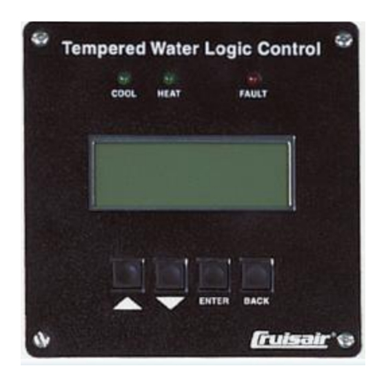
- Page 10 Display Keypad Menu-driven display screen • 4 lines of text, 20 characters per line • Cool light - Indicates Cool mode • Heat light - Indicates Heat, Reverse Cycle/Heaters, or Heaters Only modes • Fault light - Indicates system faults •...
- Page 11 Modes of Operation • Off • Cool • Heat • RevCyc/Heaters Activates compressors first when sea water is 38 F (3.33 C), compressors turn off, and immersion heaters turn on • Heaters Only – activates immersion heaters only...
- Page 12 System Screen • Displays which compressor or heater is on, disabled, or in sustained shutdown • Displays which mode the system is operating • Displays the common loop water supply temperature • Displays the loop water return temperature...
- Page 13 Main Menu Chiller Status • Displays the value of all input sensors that is connected to the board Board output status, Software version number, Unit stage on each chiller • Aids in troubleshooting the chiller system Parameter Setting • Displays heat and cool stage temperature set points and differentials (adjustable) •...
- Page 14 Main Menu (cont’d.) Degrees Fahrenheit / Celsius (selectable) Fault Log – Displays how many and what type of faults a chiller has encountered Fault History – Displays up to the latest 300 system faults on each chiller Input/Output Log • Displays compressor, water pump, heater, and reversing valve run-times •...
- Page 15 • Low AC Voltage condition What the System Monitors • Defective Temperature Sensors • Loop Water Temperatures • Extremely Low Loop Water Temperature Condition • Extremely High Loop Water Temperature Condition • Extremely High Immersion Heater Loop Water Temperature Condition •...
- Page 16 Single Chiller Unit Control Panel Standard Features • Requires 230VAC 1-PH power for control circuits • Field-configured to run 230VAC 1-PH or 3-PH, or 380/460VAC 3-PH chiller units • Does not include compressor, loop and sea water pump breakers • Includes loop and sea water pump 230VAC signal outputs to activate water pump triggers •...
- Page 17 System Faults For Version 33 and Earlier Eproms • Flow switch (opens for more than 5 seconds) Sustain shutdown after 5 faults • Loop water low temperature limit (36 F (2.22 C)) Sustained shutdown after 3 faults • Loop water high temperature limit (130 F (54.4 C)) Sustained shutdown after 3 faults •...
- Page 18 System Faults For Version 33 and Earlier Eproms (cont’d.) • Low suction refrigerant pressure (at 30 PSI) No sustained shutdown • Loss of network Defective network cable and/or chiller board; each chiller still operates independently • In and Out Loop water temperature difference limit In cool mode, if temperature difference is 14 F (7.8 C) or greater for 2 minutes, the chiller goes into sustained shutdown •...
- Page 19 System Faults for Sensors (cont’d.) •Loop water out sensor Sustained shut down on first fault •Common loop water return sensor With multiple chillers if the #1 sensor fails the system will use the next available water return sensor and the unit will continue to run. If all the return sensors fail, the system will use the common loop water supply sensor to monitor stage set points.
- Page 20 Temperature Sensors Locations For The MTC Model Units Loop water out sensor •Located on the water outlet pipe on the top of the plate coil •This sensor is used to sense the Loop water low temperature limit (Freeze sensor) •Sensor is marked (Supply) Common loop water return sensor •Located on the water inlet pipe on the bottom of the plate coil...
- Page 21 Temperature Sensors Locations For The New MTD Model Units Loop water out sensor •Sensor is inserted in a well in the back of the plate coil on the top •Sensor should be marked (Supply) Common loop water return sensor •Sensor is inserted in a well in the back of the plate coil on the bottom...
- Page 22 Temperature Sensors Locations For The New TWC Model Units Common loop water return sensor •Sensor is inserted in a well in the back of the plate coil on the top Loop water out sensor •Sensor is inserted in a well in the back of the plate coil on the bottom...
- Page 23 New TWC Model Units Units are plumbed backwards from Notice the arrow on the flow switch standard units Loop water return Loop water out or supply...
- Page 24 Common Loop Sensors Location Common loop water supply sensor •The sensor should be located on the supply line right after all the chillers are plumbed together •The sensor should always be wired up to the #1 chiller board...
- Page 25 Unit Faults out on “Loop Low Temp” version 33 and earlier “ Loop water out” temperature is at 36 degrees F or below • Go to the parameter setting screen to make sure the light load set points are in use. •...
- Page 26 Water Flow Problems • Check the water pressure on the gauge • Check for proper phase rotation on before the pump • It should read between 12-18 PSI, in 3-phase pumps • Check the common loop strainer (if some installs with 30 tons and above installed) for trash or debris may go to 20 psi max •...
- Page 27 Water Flow Problems Check the individual strainer at the inlet of the chiller barrel for trash or debris (Only on MTC or earlier models)
- Page 28 Sensors are not reading the correct temperature • Go to the chiller status screen and scroll down to “Loop Water Out” to see the temperature of the supply sensor and compare it to the actual temperature of the outlet pipe •...
- Page 29 Sensors are not reading the correct temperature Check main harness 12 pin plug for moisture and corrosion • If plugs are not to bad, clean with electronic contact cleaner and blow out with compressed air • If corroded badly, cut the plugs out and butt connect the wires and heat shrink •...
- Page 30 Unit faults out on “Loop TD Max Limit” version 33 and earlier Faults out when loop water temperature between inlet and outlet or common loop supply is more than 14 degrees F, (8C) for more than 2 minutes • Go to the chiller status screen and check the Common Loop Return against the Loop Water Out and the Common Loop Supply temperatures...
Need help?
Do you have a question about the TWLC and is the answer not in the manual?
Questions and answers