
Summary of Contents for STT Condigi CareCom IP
- Page 1 CareCom IP K1122 Installation Guide STT Condigi Agnesfridsvägen 113 A 212 37 Malmö Sweden...
-
Page 2: Table Of Contents
Power Supply and Connection to Network ......4.1 Power Supply and Network Cable .......... 4.2 Connection ..................How to add a CareCom IP Room Unit to the Swan CareCom System ............5.1 Configuring 3CX Settings ............5.2 Configuring the CareCom IP ............. -
Page 3: Introduction
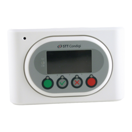
2-way conversation between the CareCom IP and the device that has given the alarm. CareCom IP is mounted on a wall and is connected to a POE switch/router. Furthermore CareCom IP has two inputs and two outputs. -
Page 4: Installation
Installation Programming Mode Installation of CareCom IP is done in the programming mode, which is accessed by holding down the red button while connecting the net- work cable. The display will then look like the illustration bellow. > Local Number... -
Page 5: Local Ip
Server IP is setup in the same way as a local number. ARM Flash/Edit Address/Set default EE These three functions are not used. Mounting CareCom IP is mounted on a wall – in the included wall bracket. The illustration is viewed from the wall. -
Page 6: Power Supply And Connection To Network
Digital Out 2 (Presence LED) Connection When the CareCom IP is connected, the small LED will flash yellow until the network is found. When the network is found, the LED will change to green for approx. one minute. After that, it will turn off. -
Page 7: How To Add A Carecom Ip Room Unit To The Swan Carecom System
OUT2 (S03.242 and S03.248). +24V How to add a CareCom IP Room Unit to the Swan CareCom System In the below mentioned examples the screen shots are only indicative. Prerequisite: The CareCom Server must be version 5.2.0 or above. The CareCom IP room unit must have firmware version 1.2.10. -
Page 8: Configuring The Carecom Ip
Remember the password as you are using this later. 5. Scroll down and click “OK” to save the changes. Configuring the CareCom IP Follow these steps to configure the CareCom IP in the ctLinkCareComServer User Interface. 1. Start the ctLinkCareComServer User Interface from the taskbar... - Page 9 2. Select the new CareCom IP and click the pencil icon to edit the configuration. 3. Set the “Input Notification” to “Input I/O Normally Open”. 4. Set the “Display Group”. 5. Click “SIP Account”. 6. Type in the Extension Number defined in the 3CX and click “OK”.
-
Page 10: Configuring The Equipment In The Swan Carecom (Televagt) Data Base
Configuring the Equipment in the Swan CareCom (TeleVagt) Data Base Follow these steps to configure the CareCom IP in the Swan CareCom (TeleVagt) Data Base. 1. Start the Swan CareCom (TeleVagt) Data Base. 2. Double click any equipment in the Customer Equipment List. - Page 11 8. Drag the correct “Call Sequence” to the field “Calling Sequence”. 9. Type in the “Extension Number” into the field “Telephone”. 10. Type “Name” and “Address” of the new CareCom IP 11. Click the menu “Save” to save the changes.
-
Page 12: Configuring The Ctcarecomserver
Configuring the ctCareComServer Follow these steps to configure the CCIP in the ctLinkCareComServer. 1. Start the ctLink Configuration Manager from the Windows programs list. 2. Click the “ctCareComServer”. 3. Ensure that “Display_AutoDisplay” is set to “Show Alarms on Presence”. 4. Ensure that “Display_NoAcknowledge” is set to “Alarms can be ac knowledged”. -
Page 13: Configuring The Ctdisplayserver
Configuring the ctDisplayServer Follow these steps to configure the CareCom IP in the “ctLinkCareComServer”. 1. Start the ctLink Configuration Manager from the Windows programs list. 2. Click the “ctDisplayServer1”. 3. Ensure “Display_AlarmServer” is set to Swan CareCom (TeleVagt). - Page 16 STT Condigi Agnesfridsvägen 113 A 212 37 Malmö Sweden www.sttcondigi.com...
Need help?
Do you have a question about the CareCom IP and is the answer not in the manual?
Questions and answers