Table of Contents
Advertisement
Advertisement
Table of Contents

Summary of Contents for Dexion HI280
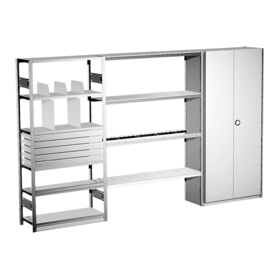
- Page 2 HI280 shelving system. HI280 is a versatile product that can be built to meet individual requirements whether these are in the length, width or height of the equipment being supplied, or in the style of the premises in which the product is being installed.
-
Page 3: Table Of Contents
MAIN CONTENTS Section A – Product Introduction. Page Basic System ........................Parameters of the System ....................Rack Dimensions........................Section B – Construction Guidelines Page Introduction .......................... Method Statements....................... Typical Construction Considerations ..................Frame Sub-Assembly ......................Build Procedure, Line and Level, and Fix Down..............Section C –... - Page 4 Section E – Frame Assembly Schedule Page Introduction ........................... Low Rise - Fixed Height Frames up to 3000mm 2 L/D Battens (swaged or riveted) ..300 to 600mm widths........... 2 H/D Battens (riveted) ......800, and 1000mm widths........3 L/D Battens (swaged or riveted) ..300 to 600mm widths........... 3 H/D Battens (riveted) ......
-
Page 5: Section A - Product Introduction
SECTION A – PRODUCT INTRODUCTION BASIC SYSTEM The Dexion HI280 shelving system is a heavy duty, versatile product available in a wide choice of sizes to enable individual solutions to be tailored to client requirements. It is quick and easy to assemble with the main components simply hooking and locking together to provide a strong rigid structure. -
Page 6: Parameters Of The System
PARAMETERS OF THE SYSTEM The Dexion HI280 product has been designed to operate within the following standard parameters. Consult product support if considering applications outside of this range. Hand Loaded HI280 is a hand loaded shelving system, which is NOT suitable for loading by fork lift truck. -
Page 7: Rack Dimensions
RACK DIMENSIONS Frame Width ‘W’ Frame widths are expressed by their nominal dimension, i.e. either 300, 400, 450, 500, 600, 800 or 1000mm. Rack Width ‘W+’ The actual rack dimensions are slightly greater than the frame dimensions: Single entry racks = nominal frame dimension + 6mm. Double entry racks = nominal combined frame dimension + 12mm. -
Page 8: Section B - Construction Guidelines Page
SECTION B – CONSTRUCTION GUIDELINES This is a guide to the considerations that must be taken into account when installing Dexion HI280 shelving. Whilst it is important to install the shelving accurately and in an efficient manner, it is of greater importance to achieve this in a safe environment. -
Page 9: Typical Construction Considerations
Typical Construction Considerations First Aid and Emergency Procedures Provision of a suitably equipped first aid box, with a proficient approved First Aider. Awareness of clients fire alarm and evacuation routes and procedures. Risk Assessments In preparing these associated risks can be highlighted, and the necessary steps taken to reduce the risks to acceptable levels. - Page 10 Measuring and Marking Out Site This should be undertaken at the beginning of each phase of the erection, using datums provided on the installation layout. Checks should be made at this early stage to ensure the shelving fits the building. Use a chalk line to mark out the site.
- Page 11 Signed: Date: Name: Position: (For and on behalf of Dexion Limited) Signed: Date: Name: Position: For and on behalf of:...
-
Page 12: Frame Sub-Assembly
Frame Sub-Assembly A jig frame is assembled in accordance with the “Frame Assembly Schedule”. All the fixings are made and the jig frame is checked for squareness. This frame is then laid on a flat bed made up from convenient materials, usually stacks of wooden pallets, at a comfortable working height. This frame then forms a template on which all subsequent frames are assembled. -
Page 13: Build Procedure, Line And Level, And Fix Down
When swaged connections are being used it is important to use the correct type of tool corresponding with the type of upright (i.e. use the ‘K’ tool for the ‘K’ upright, and the ‘EK’ for the ‘EK’ upright). If the resultant hole through the swage measures less than 9.5mm diameter, the tool is worn and needs replacing. -
Page 14: Section C - Assembly Instructions
SECTION C - ASSEMBLY INSTRUCTIONS The following pages give the assembly instructions and techniques for the HI280 shelving components and accessories. Each page deals with a separate component or aspect of the build. Where appropriate reference should be made to the separate schedule pages for the number of components required and their positioning, i.e. -
Page 15: Important Checks
ASSEMBLY INSTRUCTIONS – IMPORTANT CHECKS Swage Tool Check the condition of the swage tool for wear. If the resultant hole through the swage measures less than 9.5mm diameter, the tool is worn and should be replaced. Ensure the correct tool is being used, use the ‘K’ tool for the ‘K’ upright and the ‘EK’ tool for the ‘EK’... -
Page 16: Battened / Braced Frames
ASSEMBLY INSTRUCTIONS – BATTENED / BRACED FRAMES Note: Frame battens and braces must be positioned in accordance with the dimensions contained within the ‘frame assembly schedule’. To assist assembly we recommend the use of an assembly jig and work bench. When using swage connections ensure the swage tool corresponds to the type of upright, i.e. -
Page 17: Clad Frames
ASSEMBLY INSTRUCTIONS – CLAD FRAMES Note: To assist assembly we recommend the use of an assembly jig and work bench. When using swage connections ensure the swage tool corresponds to the type of upright, i.e. the ‘K’ tool for the ‘K’ upright and the ‘EK’ tool for the ‘EK’ upright. Insert the long edge of the cladding sheet into the open U-shaped part of the upright (1), and align the oval holes in both sheet and upright. -
Page 18: Mesh Frame Cladding
ASSEMBLY INSTRUCTIONS – MESH FRAME CLADDING Note: Mesh can only be fitted to a frame that is already either battened or battened and braced. Mesh does not replace these items. When using swage connections ensure the swage tool corresponds to the type of upright, i.e. -
Page 19: Base Plinth
ASSEMBLY INSTRUCTIONS – BASE PLINTH Note: Before assembling, check that the hooks on both the upright and base plinth are not damaged. The base plinth (which has 3 hooks at either end) is positioned between the front uprights at a height of 75mm. The back of the bottom shelf is supported as normal with a shelf beam. -
Page 20: Shelf Beam Or Medium Span Beam
ASSEMBLY INSTRUCTIONS – SHELF BEAM or MEDIUM SPAN BEAM Note: Before assembling, check that the hooks on both the upright and beams are not damaged. Use the oval and round holes in the upright as a visual guide for aligning the shelves. The height to the top of the beam, corresponds to the desired shelf height. -
Page 21: Short Span Shelf
ASSEMBLY INSTRUCTIONS – SHORT SPAN SHELF Note: Before assembling, check that the hooks on both the upright and shelves are not damaged. Ensure the bay is square before attempting to install the shelves. Place the back of the shelf on top of the rear support beam (1)(2). After step (2) the shelf should be horizontal. -
Page 22: Short Span Shelf Reinforcement
ASSEMBLY INSTRUCTIONS – SHORT SPAN SHELF REINFORCEMENT Note: Shelf reinforcement is an option that can be used to increase the strength of a shelf. The number of reinforcement bars (none, one, or two) will depend on the required loading. The reinforcement is fitted before the shelf is installed. Assemble the shelf beam at the required height between the rear uprights. -
Page 23: Medium Span Shelves
ASSEMBLY INSTRUCTIONS – MEDIUM SPAN SHELVES Note: Before assembling, check that the hooks on the rear of the beams are not damaged. Install the beams as previously described, and ensure the bay is square before attempting to install the shelves. Chipboard shelves. -
Page 24: Assembling A Double Entry Rack
ASSEMBLY INSTRUCTIONS – ASSEMBLING A DOUBLE ENTRY RACK Note: A double entry rack is when two single rows of shelving are placed back to back. Racks up to 3000mm high. Connect the back uprights together at the top, and at the bottom using M6x20mm long fixings through the holes in the face of the uprights. -
Page 25: Fixing Down A Rack
ASSEMBLY INSTRUCTIONS – FIXING DOWN A RACK Note: All racks that are fitted with either drawer or tray sets MUST be fixed to the floor. Racks that have a height to the top loaded shelf greater than 5 times the frame width MUST be fixed to the floor. -
Page 26: Solid Back Cladding
ASSEMBLY INSTRUCTIONS – SOLID BACK CLADDING Note: There are two forms of solid back cladding, either using half width sheets (as shown above), or using a number of full width sheets within the height. Both use the same method of cladding clip to fix the cladding to the uprights. The clips pass through the punched rectangular hooks along the edges of the cladding sheet. -
Page 27: Mesh Back Cladding
ASSEMBLY INSTRUCTIONS – MESH BACK CLADDING Note: The clip used for attaching mesh back cladding is the same as that used for the solid sheet cladding. Place the mesh sheet between the rear uprights. Hook the clips around the wire, and press the clip into upright as shown above. Each panel is secured with 8 clips, 4 either side. -
Page 28: Accessories
ASSEMBLY INSTRUCTIONS – ACCESSORIES Tube rail Can be used singularly, or as a pair. First hook a tube rail support to each frame at the desired height, then hook the tube rails over these supports Bay divider Hook the divider bracket over the rear beam. For safety ensure the divider arm is fitted with its plastic protective end plug. -
Page 29: Decorative End Frame Cladding
ASSEMBLY INSTRUCTIONS – DECORATIVE END FRAME CLADDING Note: This type of frame cladding is only fitted to the end frames of each rack. The panel is slid in from the top, taking care not to damage the decorative finish. Issue: June 2005 Section C –Assembly Instructions Page C.16... -
Page 30: Bench Top And Tool Panel
ASSEMBLY INSTRUCTIONS – BENCH TOP and TOOL PANEL Revised illustration Note: The bench top and tool panel kit is designed to fit within a 1500 x 500mm bay. Assemble the components in numeric order as they appear above. Position the beams (1) to give a comfortable working height for the bench top (3). The bench top locks (2) should be positioned as close to the rear corners as possible and each secured with a 4.8x7 SST rivet into either of the holes in the upright web. -
Page 31: Drawers And Trays
ASSEMBLY INSTRUCTIONS – DRAWERS and TRAYS Note: All racks fitted with either drawers or trays MUST be securely fixed to the floor to eliminate the risk of overturning. The expansion slides, and slide holders both come in left and right hand options. Assemble 4 expansion slide holders (1)(2), making sure they are securely fixed to the upright with a M5x16mm long nut and bolt through the web of the upright. -
Page 32: Door Sets
ASSEMBLY INSTRUCTIONS – DOOR SETS Position the top and bottom pieces by sliding them over the front edge of the respective top and bottom shelves. The angle bracket on the front face of each piece is always positioned to the right hand side. Secure each piece with two black expanding fixings. -
Page 33: Section D - Rack Erection Tolerances Page
SECTION D – RACK ERECTION TOLERANCES HI280 is a hand loaded shelving system, which will generally be used in applications where it can be accessed either direct from floor level, or via small steps. However it also has the ability to be built to heights of 12,000mm, where it will be operated by “man-up”... - Page 34 The following is a summary of the notations given to the individual tolerances and how they relate to Classes 400 and 300 A. Issue: June 2005 Section D – Rack Erection Tolerances Page D.2...
- Page 35 FEM 10.3.01 Rack Erection Tolerances Ref. Description (n = No of bays) Tolerance Class 300A Horizontal Tolerances Maximum variation in individual bays ± 3mm ± 3mm Total deviation in rack length cumulative per bay ± 3.0n ± 3.0n Length difference between two rows of bays at each side ±10mm ±10mm of an aisle;...
-
Page 36: Low Rise - Fixed Height Frames Up To 3000Mm
SECTION E – FRAME ASSEMBLY SCHEDULE This section provides detailed dimensions of how the frames should be constructed, where to position the horizontal battens, and the location of frame bracing node points. The strength data that these racks will have been designed to is a result of extensive tests and calculation and involves the correct positioning of battens, braces, and fixings. -
Page 37: Multi-Tier Frames Fixed Height Up To 3000Mm 2300Mm Multi-Tier (Braced + L/D Swaged Battens)
Multi-Tier Frames Fixed Height up to 3000mm 2300mm Multi-Tier (Braced + L/D swaged battens) 300 to 600mm widths. E.40 2300mm Multi-Tier (Braced + L/D riveted battens) 300 to 600mm widths. E.41 2300mm Multi-Tier (Braced + H/D riveted battens) 800 and 1000mm widths. E.42 2500mm Multi-Tier (Braced + L/D swaged battens) 300 to 600mm widths. - Page 38 LOW RISE - 2 LIGHT DUTY BATTENS (swaged or riveted). Component take-off Quantity Upright Baseplate Upright to baseplate fixing (when required) Light duty batten Rivet 4.8 x 7mm (only for riveted frames) Frame First Batten Height Batten Centres Batten ‘H’ ‘A’...
- Page 39 LOW RISE - 2 HEAVY DUTY BATTENS (riveted). Component take-off Quantity Upright Baseplate Upright to baseplate fixing (when required) Heavy duty batten Rivet 4.8 x 7mm Frame First Batten Height Batten Centres Batten ‘H’ ‘A’ ‘B’ ‘C’ 1000mm 1600mm 2100mm 1300 2300mm 1500...
- Page 40 LOW RISE - 3 LIGHT DUTY BATTENS (swaged or riveted). Component take-off Quantity Upright Baseplate Upright to baseplate fixing (when required) Light duty batten Rivet 4.8 x 7mm (only for riveted frames) Frame First Batten Batten Height Batten Centres Centres Batten ‘H’...
- Page 41 LOW RISE - 3 HEAVY DUTY BATTENS (riveted). Component take-off Quantity Upright Baseplate Upright to baseplate fixing (when required) Heavy duty batten Rivet 4.8 x 7mm Frame First Batten Batten Height Batten Centres Centres Batten ‘H’ ‘A’ ‘B’ ‘C’ ‘D’ 2100mm 2300mm 2500mm...
- Page 42 LOW RISE - 4 LIGHT DUTY BATTENS (swaged or riveted). Component take-off Quantity Upright Baseplate Upright to baseplate fixing (when required) Light duty batten Rivet 4.8 x 7mm (only for riveted frames) Frame First Batten Batten Batten Height Batten Centres Centres Centres Batten...
- Page 43 LOW RISE - 4 HEAVY DUTY BATTENS (riveted). Component take-off Quantity Upright Baseplate Upright to baseplate fixing (when required) Heavy duty batten Rivet 4.8 x 7mm Frame First Batten Batten Batten Height Batten Centres Centres Centres Batten ‘H’ ‘A’ ‘B’ ‘C’...
- Page 44 LOW RISE - 4 LIGHT DUTY BATTENS (swaged) + 2 ‘X’ BRACES. Component take-off Quantity Upright Baseplate Upright to baseplate fixing (when required) Light duty batten (swage holes) Frame brace Rivet 4.8 x 7mm Issue: June 2005 Section E – Frame Assembly Schedule Page E.9...
- Page 45 LOW RISE - 4 LIGHT DUTY BATTENS (riveted) + 2 ‘X’ BRACES. Component take-off Quantity Upright Baseplate Upright to baseplate fixing (when required) Light duty batten (rivet holes) Frame brace Rivet 4.8 x 7mm Issue: June 2005 Section E – Frame Assembly Schedule Page E.10...
- Page 46 LOW RISE - 3 HEAVY DUTY BATTENS (riveted) + 2 ‘X’ BRACES. Component take-off Quantity Upright Baseplate Upright to baseplate fixing (when required) Heavy duty batten Frame brace Rivet 4.8 x 7mm Issue: June 2005 Section E – Frame Assembly Schedule Page E.11...
- Page 47 HIGH RISE - 4 LIGHT DUTY BATTENS (swaged or riveted). Component take-off Quantity Upright Baseplate Upright to baseplate fixing (when required) Light duty batten Rivet 4.8 x 7mm (only for riveted frames) The chart containing the schedule of dimensions is shown on the following page. Issue: June 2005 Section E –...
- Page 48 HIGH RISE - 4 LIGHT DUTY BATTENS (swaged or riveted) (continued). Frame First Batten Batten Batten Height Batten Centres Centres Centres Batten ‘H’ ‘A’ ‘B’ ‘C’ ‘D’ ‘E’ 3100mm 3200mm 1000 3300mm 1000 1000 3400mm 1000 1000 3500mm 1000 1100 3600mm 1100 1100...
- Page 49 HIGH RISE - 4 HEAVY DUTY BATTENS (riveted). Component take-off Quantity Upright Baseplate Upright to baseplate fixing (when required) Heavy duty batten Rivet 4.8 x 7mm The chart containing the schedule of dimensions is shown on the following page. Issue: June 2005 Section E –...
- Page 50 HIGH RISE - 4 HEAVY DUTY BATTENS (riveted) (continued). Frame First Batten Batten Batten Height Batten Centres Centres Centres Batten ‘H’ ‘A’ ‘B’ ‘C’ ‘D’ ‘E’ 3100mm 3200mm 1000 3300mm 1000 1000 3400mm 1000 1000 3500mm 1000 1100 3600mm 1100 1100 3700mm 1100...
- Page 51 HIGH RISE - 5 LIGHT DUTY BATTENS (swaged or riveted). Component take-off Quantity Upright Baseplate Upright to baseplate fixing (when required) Light duty batten Rivet 4.8 x 7mm (only for riveted frames) The chart containing the schedule of dimensions is shown on the following page. Issue: June 2005 Section E –...
- Page 52 HIGH RISE - 5 LIGHT DUTY BATTENS (swaged or riveted) (continued). Frame First Batten Batten Batten Batten Height Batten Centres Centres Centres Centres Batten ‘H’ ‘A’ ‘B’ ‘C’ ‘D’ ‘E’ ‘F’ 3100mm 3200mm 3300mm 3400mm 3500mm 3600mm 3700mm 1000 3800mm 1000 3900mm 1100...
- Page 53 HIGH RISE - 5 HEAVY DUTY BATTENS (riveted). Component take-off Quantity Upright Baseplate Upright to baseplate fixing (when required) Heavy duty batten Rivet 4.8 x 7mm (only for riveted frames) The chart containing the schedule of dimensions is shown on the following page. Issue: June 2005 Section E –...
- Page 54 HIGH RISE - 5 HEAVY DUTY BATTENS (riveted) (continued). Frame First Batten Batten Batten Batten Height Batten Centres Centres Centres Centres Batten ‘H’ ‘A’ ‘B’ ‘C’ ‘D’ ‘E’ ‘F’ 3100mm 3200mm 3300mm 3400mm 3500mm 3600mm 3700mm 1000 3800mm 1000 3900mm 1100 4000mm 1100...
- Page 55 HIGH RISE - 4 HEAVY DUTY BATTENS (riveted) + 2 ‘X’ BRACES. Component take-off Quantity Upright Baseplate Upright to baseplate fixing (when required) Heavy duty batten Frame brace Rivet 4.8 x 7mm Frame Height 3100mm 3200mm 3300mm 3400mm Dimension ‘A’ 300mm 400mm 400mm...
- Page 56 HIGH RISE - 5 LIGHT DUTY BATTENS (swaged) + 2 ‘X’ BRACES. Component take-off Quantity Upright Baseplate Upright to baseplate fixing (when required) Light duty batten (swage holes) Frame brace Rivet 4.8 x 7mm The chart containing the schedule of dimensions is shown on the following page. Issue: June 2005 Section E –...
- Page 57 HIGH RISE - 5 LIGHT DUTY BATTENS (swaged) + 2 ‘X’ BRACES (continued). Frame Batten Batten Height Centres Centres ‘H’ ‘A’ ‘B’ 3100mm 3200mm 3300mm 3400mm 3500mm 3600mm 3700mm 3800mm 3900mm 4000mm 4100mm 4200mm 4300mm 1000 4400mm 1000 4500mm 1100 4600mm 1100 4700mm...
- Page 58 HIGH RISE - 5 LIGHT DUTY BATTENS (riveted) + 2 ‘X’ BRACES. Component take-off Quantity Upright Baseplate Upright to baseplate fixing (when required) Light duty batten (rivet holes) Frame brace Rivet 4.8 x 7mm The chart containing the schedule of dimensions is shown on the following page. Issue: June 2005 Section E –...
- Page 59 HIGH RISE - 5 LIGHT DUTY BATTENS (riveted) + 2 ‘X’ BRACES (continued). Frame Batten Batten Height Centres Centres ‘H’ ‘A’ ‘B’ 3100mm 3200mm 3300mm 3400mm 3500mm 3600mm 3700mm 3800mm 3900mm 4000mm 4100mm 4200mm 4300mm 1000 4400mm 1000 4500mm 1100 4600mm 1100 4700mm...
- Page 60 HIGH RISE - 5 HEAVY DUTY BATTENS (riveted) + 2 ‘X’ BRACES. Component take-off Quantity Upright Baseplate Upright to baseplate fixing (when required) Heavy duty batten Frame brace Rivet 4.8 x 7mm The chart containing the schedule of dimensions is shown on the following page. Issue: June 2005 Section E –...
- Page 61 HIGH RISE - 5 HEAVY DUTY BATTENS (riveted) + 2 ‘X’ BRACES (continued). Frame Batten Batten Height Centres Centres Batten ‘H’ ‘A’ ‘B’ ‘C’ 3500mm 3600mm 3700mm 3800mm 3900mm 4000mm 4100mm 4200mm 4300mm 4400mm 4500mm 4600mm 4700mm 4800mm 4900mm 5000mm 1000 5100mm 1000...
- Page 62 HIGH RISE – FULLY BRACED with LIGHT DUTY BATTENS (swaged). ‘H’ = Frame height, ‘N’ = required number of bracing panels. A Fully Braced frame consists of a number of standard height bracing panels, plus the possibility of either one or two additional horizontal battens. See ‘#’ above. When using light duty swaged battens the bracing panel height is 1000mm.
- Page 63 HIGH RISE – FULLY BRACED with LIGHT DUTY BATTENS (swaged) (continued). Frame No. of No. of Batten centres (mm) Material take-off height panels extra battens braces rivets ‘H’ ‘N’ battens ‘A’ ‘B’ ‘C’ 3100mm 3200mm 3300mm 3400mm 3500mm 3600mm 3700mm 3800mm 3900mm 4000mm...
- Page 64 HIGH RISE – FULLY BRACED with LIGHT DUTY BATTENS (swaged) (continued). Frame No. of No. of Batten centres (mm) Material take-off height panels extra battens braces rivets ‘H’ ‘N’ battens ‘A’ ‘B’ ‘C’ 7600mm 7700mm 7800mm 7900mm 8000mm 8100mm 8200mm 8300mm 8400mm 8500mm...
- Page 65 HIGH RISE – FULLY BRACED with LIGHT DUTY BATTENS (riveted). ‘H’ = Frame height, ‘N’ = required number of bracing panels. A Fully Braced frame consists of a number of standard height bracing panels, plus the possibility of either one or two additional horizontal battens. See ‘#’ above. When using light duty riveted battens the bracing panel height is 1100mm.
- Page 66 HIGH RISE – FULLY BRACED with LIGHT DUTY BATTENS (riveted) (continued). Frame No. of No. of Batten centres (mm) Material take-off height panels extra battens braces rivets ‘H’ ‘N’ battens ‘A’ ‘B’ ‘C’ ‘D’ 3100mm 3200mm 3300mm 3400mm 3500mm 3600mm 3700mm 3800mm 3900mm...
- Page 67 HIGH RISE – FULLY BRACED with LIGHT DUTY BATTENS (riveted) (continued). Frame No. of No. of Batten centres (mm) Material take-off height panels extra battens braces rivets ‘H’ ‘N’ battens ‘A’ ‘B’ ‘C’ ‘D’ 7600mm 7700mm 7800mm 7900mm 8000mm 8100mm 8200mm 8300mm 8400mm...
- Page 68 HIGH RISE – FULLY BRACED with HEAVY DUTY BATTENS (riveted). ‘H’ = Frame height, ‘N’ = required number of bracing panels. A Fully Braced frame consists of a number of standard height bracing panels, plus the possibility of either one or two additional horizontal battens. See ‘#’ above. When using heavy duty riveted battens the bracing panel height is 1200mm.
- Page 69 HIGH RISE – FULLY BRACED with HEAVY DUTY BATTENS (riveted) (continued). Frame No. of No. of Batten centres (mm) Material take-off height panels extra battens braces rivets ‘H’ ‘N’ battens ‘A’ ‘B’ ‘C’ ‘D’ 3100mm 3200mm 3300mm 3400mm 3500mm 3600mm 3700mm 3800mm 3900mm...
- Page 70 HIGH RISE – FULLY BRACED with HEAVY DUTY BATTENS (riveted) (continued). Frame No. of No. of Batten centres (mm) Material take-off height panels extra battens braces rivets ‘H’ ‘N’ battens ‘A’ ‘B’ ‘C’ ‘D’ 7600mm 7700mm 7800mm 7900mm 8000mm 8100mm 8200mm 8300mm 8400mm...
- Page 71 FULLY SOLID CLAD FRAMES. ‘H’ = Frame height, ‘N’ = required number of cladding sheets. Each cladding sheet must be secured with either swage or rivet connections, positioned at the top, the bottom and the rest evenly distributed in between at no more than 400mm centres. For a 900mm sheet use 6 connections, 1000mm = 8, 1600mm = 10, 2100mm = 12, 2300mm = 14, and 2500mm = 14 connections.
- Page 72 FULLY SOLID CLAD FRAMES (continued). Frame No. of No. of No. of Quantity of each cladding sheet type height clad clad swage 1000 1600 2100 2300 2500 ‘H’ sheets trim fixings 1000mm 1600mm 2100mm 2300mm 2500mm 3000mm 3100mm 3200mm 3300mm 3400mm 3500mm 3600mm...
- Page 73 FULLY SOLID CLAD FRAMES (continued). Frame No. of No. of No. of Quantity of each cladding sheet type height clad clad swage 1000 1600 2100 2300 2500 ‘H’ sheets trim fixings 6000mm 6100mm 6200mm 6300mm 6400mm 6500mm 6600mm 6700mm 6800mm 6900mm 7000mm 7100mm...
- Page 74 FULLY SOLID CLAD FRAMES (continued). Frame No. of No. of No. of Quantity of each cladding sheet type height clad clad swage 1000 1600 2100 2300 2500 ‘H’ sheets trim fixings 10000mm 10100mm 10200mm 10300mm 10400mm 10500mm 10600mm 10700mm 10800mm 10900mm 11000mm 11100mm...
- Page 75 2300mm MULTI-TIER FRAME (Braced + Light duty swaged battens). Component take-off Quantity Upright Baseplate Upright to baseplate fixing (when required) Light duty batten (swage holes) Frame brace for an 800mm high bracing panel Rivet 4.8 x 7mm Issue: June 2005 Section E –...
- Page 76 2300mm MULTI-TIER FRAME (Braced + Light duty riveted battens). Component take-off Quantity Upright Baseplate Upright to baseplate fixing (when required) Light duty batten (rivet holes) Frame brace for an 800mm high bracing panel Rivet 4.8 x 7mm Issue: June 2005 Section E –...
- Page 77 2300mm MULTI-TIER FRAME (Braced + Heavy duty riveted battens). Component take-off Quantity Upright Baseplate Upright to baseplate fixing (when required) Heavy duty batten (rivet holes) Frame brace for a 500mm high bracing panel Frame brace for an 800mm high bracing panel Rivet 4.8 x 7mm Issue: June 2005 Section E –...
- Page 78 2500mm MULTI-TIER FRAME (Braced + Light duty swaged battens). Component take-off Quantity Upright Baseplate Upright to baseplate fixing (when required) Light duty batten (swage holes) Frame brace for an 800mm high bracing panel Rivet 4.8 x 7mm Issue: June 2005 Section E –...
- Page 79 2500mm MULTI-TIER FRAME (Braced + Light duty riveted battens). Component take-off Quantity Upright Baseplate Upright to baseplate fixing (when required) Light duty batten (rivet holes) Frame brace for an 800mm high bracing panel Rivet 4.8 x 7mm Issue: June 2005 Section E –...
- Page 80 2500mm MULTI-TIER FRAME (Braced + Heavy duty riveted battens). Component take-off Quantity Upright Baseplate Upright to baseplate fixing (when required) Heavy duty batten (rivet holes) Frame brace for a 500mm high bracing panel Frame brace for an 800mm high bracing panel Rivet 4.8 x 7mm Issue: June 2005 Section E –...
- Page 81 3000mm MULTI-TIER FRAME (Braced + Light duty swaged battens). Component take-off Quantity Upright Baseplate Upright to baseplate fixing (when required) Light duty batten (swage holes) Frame brace for a 500mm high bracing panel Frame brace for an 800mm high bracing panel Rivet 4.8 x 7mm Issue: June 2005 Section E –...
- Page 82 3000mm MULTI-TIER FRAME (Braced + Light duty riveted battens). Component take-off Quantity Upright Baseplate Upright to baseplate fixing (when required) Light duty batten (rivet holes) Frame brace for an 800mm high bracing panel Rivet 4.8 x 7mm Issue: June 2005 Section E –...
- Page 83 3000mm MULTI-TIER FRAME (Braced + Heavy duty riveted battens). Component take-off Quantity Upright Baseplate Upright to baseplate fixing (when required) Heavy duty batten (rivet holes) Frame brace for an 800mm high bracing panel Rivet 4.8 x 7mm Issue: June 2005 Section E –...
- Page 84 SECTION F – FULL WIDTH BACK CLADDING SCHEDULE This section details the combination of ‘Full Width Back Cladding Panels’ required to equip each rack height. Individual panels have a nominal height of either 800, 1000, 1200, or 1300mm. Each panel is secured to the uprights with 6 back cladding clips, three either side of the panel. The hook on the clip passes through the rectangular hooks punched along the edges of the panel.
- Page 85 FULL WIDTH BACK CLADDING SCHEDULE (continued) Rack No. of No. of No. of Quantity of each cladding sheet type height cladding cladding cladding 1000 1200 1300 ‘H’ sheets trims clips 1000mm 1600mm 2100mm 2300mm 2500mm 3000mm 3100mm 3200mm 3300mm 3400mm 3500mm 3600mm 3700mm...
- Page 86 FULL WIDTH BACK CLADDING SCHEDULE (continued) Rack No. of No. of No. of Quantity of each cladding sheet type height cladding cladding cladding 1000 1200 1300 ‘H’ sheets trims clips 6000mm 6100mm 6200mm 6300mm 6400mm 6500mm 6600mm 6700mm 6800mm 6900mm 7000mm 7100mm 7200mm...
- Page 87 FULL WIDTH BACK CLADDING SCHEDULE (continued) Rack No. of No. of No. of Quantity of each cladding sheet type height cladding cladding cladding 1000 1200 1300 ‘H’ sheets trims clips 10000mm 10100mm 10200mm 10300mm 10400mm 10500mm 10600mm 10700mm 10800mm 10900mm 11000mm 11100mm 11200mm...
Need help?
Do you have a question about the HI280 and is the answer not in the manual?
Questions and answers