Table of Contents
Advertisement
Quick Links
Revision: 17.7 - 04/12/2012
Install Time: 30 to 90 Minutes
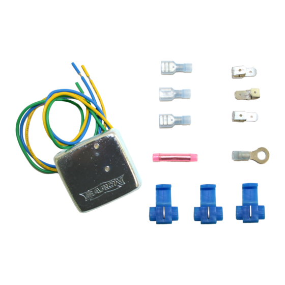
INCLUDED IN THE KIT:
(1) Chrome Billet Baron Tachometer (Black or White
Face)
(1) Ring Terminal
(1) Double-Crimp Butt Connectors
(3) Piggy-back Spade Connectors
TOOLS REQUIRED:
5/32" Allen Wrench
24" of 20 GA. Wire (Color is irrelevant)
Wire Crimper/Pliers
INSTRUCTIONS:
GENERAL WIRING INSTRUCTIONS:
GREEN WIRE provides the RPM count
BLUE or YELLOW wire provides power for the illumination
RED wire provides power to the Tach
BLACK wire is for ground
INSTALLER NOTES: Reference to LED Control Box is only relevant if you are installing a 7-Color Tachometer, otherwise only worry about the wires
from the Tachometer. To determine if your bikes requires this unit and how to determine the negative side of the coil or to determine if your bike
requires the single fire adapter see FAQ page of this document.
GREEN wire to NEGATIVE terminal of coil.
BLACK wires from Tach and LED Control box both to CHASSIS (Ground)
RED wires from Tach and LED Control box both to POSITIVE terminal of coil (or other switched 12 volt source)
BLUE or YELLOW wire from the Tach go to POSITIVE terminal of coil (or other switched 12 volt source)
7-COLOR TACHOMETERS ONLY
WHITE Connector from Tach to White Connector on LED Control Box
BLACK Switch w/RED button plugs into the LED Control Box WIRING NOTE: If you are equipped to solder your connections we recommend you do
so only after first connecting and testing the tachometer for proper operation.
INSTALLER NOTES: On some models the supplied wiring leads may need to be trimmed to fit the bikes connectors. Use the Ring Terminal for all
chassis ground connections. If you mount your Tach high up on the handlebar, or have tall or pullback risers or wide handlebars, you may need to
splice extra wire to each colored wire lead of your Tachometer prior to completing the routing and connection, then trim to appropriate length.
GENERAL MOUNTING INFORMATION
1. Mount new Baron Tach on handlebar in your preferred position. Ideal location is between handlebar risers. If mounted off-center, you can rotate
Tach face back to vertical (or any position you desire) by first loosening Tach unit's set screw (located in handlebar clamp area of the Bullet housing or
on the underside of the Mini-Bullet housing). Unscrew the housing's bezel (counterclockwise) then rotate the Tach Face to the desired position,
re-tighten the set screw and re-install the bezel.
2. Secure handlebar clamp by first tightening the flat/front dial side of clamp and then the pointed/rear side of clamp until housing does not rotate
under mild pressure. There must be a small gap on the pointed side and no gap on the flat side when the clamp is correctly tightened.
Our install guides provide a basic outline on the proper installation of our products. Further tuning and/or
fitment may be required. Barons bears no responsibility on installation costs associated with this product.
5221 Oceanus Drive
Huntington Beach, CA 92649
BA-757x-xx
BULLET & MINI-BULLET TACHOMETERS INSTALLATION
GUIDE - Please see appropriate section for your specific
application
Go slowly and follow instructions carefully. The installation is very easy if the
(3) Blue 3M Scotch-Lock Connectors
(3) Spade Connectors
(1) 3-wire BA-7315-50 BARON Tachometer Adapter
(1) LED Control Box (only included with 7-color
Tachometer)
Electrician Tape
Factory Service Manual
© 2018 Barons Custom Accessories
(925)583-2499 - Ph.
(714)901-0520 - Fax
wire color destinations are followed.
www.baronscustom.com
Page: 1
tech@baronscustom.com
Advertisement
Table of Contents

Summary of Contents for Baron BA-757 series
-
Page 1: Tools Required
GENERAL MOUNTING INFORMATION 1. Mount new Baron Tach on handlebar in your preferred position. Ideal location is between handlebar risers. If mounted off-center, you can rotate Tach face back to vertical (or any position you desire) by first loosening Tach unit's set screw (located in handlebar clamp area of the Bullet housing or on the underside of the Mini-Bullet housing). - Page 2 2004 - 2010 HARLEY-DAVIDSONS ALL MODELS REQUIRE TACH ADAPTER TACH ADAPTER: The 2004-2010 Harley Davidson will need to utilize the Baron Tach Adapter (BA-7315-50 which is included with your Tach Kit). 1. Remove the seat & fuel tank per the factory service manual.
- Page 3 WIRING INSTRUCTIONS: Wire Baron's Tach to one of your motorcycles ignition coils via the following method: GREEN WIRE from Tach to NEGATIVE terminal of coil (or direct to Green from the Tach Adapter if your bike requires the single fire adapter.
- Page 4 Q: My Tach face has fogged up, what do I do? A: Tach fogging can occur when the outside air temp is warmer than the inside of the Tach, and humidity is high. Baron Tachs feature hidden vent holes in the Tach body, these are located next to the wire exit point on the pointed end of the bar-clamp. It is important the clamp be tightened so the holes are not closed off at the pointed/rear side of the clamp and so an open air exchange can occur.
- Page 5 Wire Strippers INSTRUCTIONS: Note: This part may also work with other manufactures tachometers, although we cannot guarantee its functionality unless it is used with a Baron Tach. TACH ADAPTER KNOWN FITMENT We have tested this adapter and determined: IT IS REQUIRED ON All 2004 - 2010 HARLEY DAVIDSON models, YAMAHA V-Star 950 & 1300, 2008-2010 Road Star, Warrior, Roadliner, Stratoliner, Raider, HONDA VTX1800 , KAWASAKI VN900 &...
- Page 6 BA-7315-50 Page: 6 TACHOMETER ADAPTER (Single Fire) IT IS NOT REQUIRED ON 1980-2003 HARLEY DAVIDSON models using the stock Tach output from the bike (PINK wire), YAMAHA Road Star, Royal Star, RSTD, Venture or 1998 to 2010 Vstar 650 & 1100, KAWASAKI VN1500/VN1600 Models, HONDA VTX1300 Make connections as follows: YELLOW wire of adapter to NEGATIVE on front coil (use the spade connector and the piggyback on your...
Need help?
Do you have a question about the BA-757 series and is the answer not in the manual?
Questions and answers