
Summary of Contents for SEAWARD Electronic Rigel 266 Plus
- Page 1 Rigel 266 Plus Compact Electrical Medical Safety Analyser Instruction Manual 350A555 Issue 1.0 February 2006 © 2006 Seaward Electronic Ltd. Issue 1.0...
- Page 3 Limited Warranty & Limitation of Liability Rigel Medical, part of SEAWARD Electronic Limited guarantees this product for a period of 1 year. The period of warranty will be effective at the day of delivery. © Copyright 2006 All rights reserved. Nothing from this edition may be multiplied, or made public in any form or manner, either electronically, mechanically, by photocopying, recording, or in any manner, without prior written consent from SEAWARD Electronic Limited.
-
Page 4: Table Of Contents
Table of Contents Declaration of Conformity............4 Before Starting................5 Safety..................6 CHAPTER 1 INTRODUCING THE ANALYSER.... 8 Introduction................8 Your compact medical safety analyser ........9 The Top Panel..............9 ....................10 The Keyboard ................10 Definitions................11 CHAPTER 2 USING THE ANALYSER......12 Introduction................12 Controls .................12 Display................12 Connecting the Analyser ............14 Performing a Test ..............16 After a Test..............16... - Page 5 Patient Auxiliary, normal condition........ 36 Patient Auxiliary, single fault, supply open....36 Patient Auxiliary, single fault, earth open...... 37 IEC Lead Polarity Test ............37 CHAPTER 3 MANUAL MODE ........38 Operation:................38 CHAPTER 4 TIPS & TROUBLESHOOTING....41 Power On Self tests:..............41 Safety Tests During Operation..........
-
Page 6: Declaration Of Conformity
Rigel 266 Plus Electrical Medical Safety Analyser Manufactured by: Seaward Electronic Ltd, Bracken Hill, South West Industrial Estate Peterlee, County Durham, SR8 2SW, England Millennium Statement This product is Millennium compliant, and conforms fully to the document BSI DISC PD2000-1. -
Page 7: Before Starting
Before Starting Before Starting Upon receipt of your Rigel-266 Plus Analyser:- Check that all the component parts are present:- • Rigel 266 plus Analyser • Mains lead • Earth Bond lead • Applied Parts Lead • Applied Parts Adaptors (5 Off) & Crocodile Clip •... -
Page 8: Safety
Safety Safety Note Please read the following Safety Instructions before use! Safety Precautions The manual contains specific warning and caution statements where they apply. A Warning will identify the conditions and actions that pose hazard(s) to the user. A Caution will identify the conditions and actions that may damage the Analyser. Symbols used within this manual and on the Analyser are shown below: Risk of electric shock Warning of potential... - Page 9 Safety is essential that this manual is read fully before proceeding with any tests. Should the Analyser behave abnormally do not continue with the testing. Disconnect immediately and contact Rigel Medical for servicing (see Chapter 4 - Maintaining the Analyser).
-
Page 10: Chapter 1 Introducing The Analyser
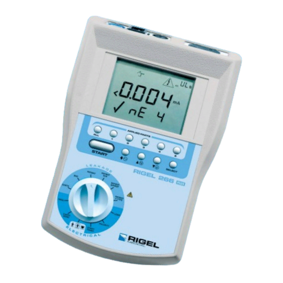
Introduction Chapter 1 Introducing the Analyser Introduction The Rigel-266 plus Electrical Medical Safety Analyser (EMSA) is a powerful tool to assist in the analysis of the safety of portable electrical and electronic medical equipment. A range of tests are provided, with innovative features to aid difficult test situations, which allow testing of a wide variety of equipment. -
Page 11: Your Compact Medical Safety Analyser
Your compact medical safety analyser Your compact medical safety analyser Item Number Part Rigel-266 plus EMSA Carrying case Earth Bond Lead Power cord - Integral with the Rigel 266 plus Applied Part Lead Set (including Applied Parts adaptors pack) Manual The Top Panel... -
Page 12: The Keyboard
Item Number Part EUT Mains Socket Applied Parts Socket Printer Interface 230V Mains Socket/Mains Input IEC Lead Connector Earth Bond Socket SIP/SOP Socket The Keyboard Item Part Rotary Test Selection Switch Semiautomatic Mode - Up Down Cursor keys Manual Mode [UP] – SFC Neutral Open, [DOWN] – SFC Earth Open, [DOWN] –... -
Page 13: Definitions
Analyser / Tester - The Rigel 266 plus compact medical electrical safety analyser. Un-powered Tests - The EUT is the subject of electrical tests using stimuli generated within the Analyser. -
Page 14: Chapter 2 Using The Analyser
Introduction Chapter 2 Using the Analyser Introduction Controls A rotary switch defines the basic test (or action) to be performed. The tests are arranged on the switch such that a clockwise rotation of the switch needed to perform a normal sequence of tests. Arrow keys ( ↑... - Page 15 Introduction The display consists of a number of Icons to provide visual indication of the Analyser status, a primary 4 digit, 7 segment display, along with a 4 digit secondary display, and a 2 digit duration time display. Test Icons Indicates the test selected, Earth Continuity Insulation...
-
Page 16: Connecting The Analyser
Connecting the Analyser Test in Progress Icon Indicates test in progress with voltage warning. Low Voltage High Voltage Applying Mains Power Test Duration Counter Indicates the duration of the test. This will count down to zero. When the counter reaches zero. The test counter can be set to unlimited test duration (indicated by “UL”... - Page 17 Connecting the Analyser...
-
Page 18: Performing A Test
Performing a Test Performing a Test Tests can be performed in two different ways i.e. in Semi-automatic mode or in Manual mode. On power up the Analyser will be in Semi-automatic test mode. The user is required to select manual test mode from the Equipment Select rotary switch position. -
Page 19: Equipment Type
START / After this has been done, all test results are then printed until the rotary switch is placed in the FINISH position again and the START button is pressed to initiate the final part of the results print-out. The user is required to manually write such items as the appliance number, date etc, and to sign off the printout where necessary. -
Page 20: Insulation Tests
Insulation Tests Class 1 (earthed) appliances Plug EUT into Analyser outlet socket, connect the Earth Bond lead to the appliance metal part. Class 2 (unearthed) appliances This test cannot be performed as there is no earth connection to exposed conductive parts of the EUT. Pressing the Start button in this instance will not initiate the test. - Page 21 Insulation Tests This test is used to verify that the mains supply pins and applied parts are adequately insulated from earth. During the insulation test, a 500V DC voltage is applied between the earth pin and both the live and neutral pins (EUT test selected) of the appliance mains supply plug or between all Applied Parts and Earth (AP test selected).
-
Page 22: Powered Tests
Powered Tests Powered Tests Warning Mains voltage applied to appliance The following powered tests differ from the previous tests in that they apply mains supply voltage to the appliance to perform their functions:- • Load (Operation) Test • Earth Leakage Test •... - Page 23 Load Test Plug EUT into Analyser outlet socket. The Load test supplies the equipment under test (appliance), connected to 230V test sockets, with the rated voltage of that socket. The Analyser measures the power used by the appliance and displays the reading in kVA. Power to the appliance can be set to remain on until the rotary switch is moved by selecting ‘UL’...
-
Page 24: Earth Leakage Test
Earth Leakage Test Earth Leakage Test EARTH Switch Position ------------ Test Icon Displayed --- Warning Mains voltage applied to appliance NOTE: The Earth bond probe should not be used as part of these tests as this may affect the current being measured. -
Page 25: Earth Leakage, Normal Condition
Earth Leakage Test The earth leakage tests are valid for Class I equipment with Types B, BF and CF applied parts. The above diagram shows the test circuit used to measure the Earth leakage current. Earth Leakage, normal condition This test measures the earth leakage current under normal conditions. The current is measured through the Measuring Device with S1 closed and S5 normal and then S5 reversed. -
Page 26: Enclosure Leakage Test
Enclosure Leakage Test measured through the Measuring Device with S1 open and S5 in normal and then S5 reversed. The maximum allowed values are as follows: Type B Type BF Type CF 1 mA 1 mA 1 mA Maximum allowed value Enclosure Leakage Test Switch Position ------------... -
Page 27: Enclosure Leakage, Normal Condition
Enclosure Leakage Test EUT Power Break 4. rP 3. rP Reversed Neutral Open EUT Power Break 5. rEV 4. rEV Reversed None 6. rE Reversed Earth Open Note: Tests marked * are not performed for Class II equipment. The user can press START at any time to start the test. During the test a screen showing test icon, test time countdown and test settings will be displayed. -
Page 28: Enclosure Leakage, Single Fault, Earth Open
Enclosure Leakage Test Class I 0.5 mA 0.5 mA 0.5 mA Class II 0.5 mA 0.5 mA 0.5 mA Enclosure Leakage, single fault, earth open This test measures the enclosure leakage current with a single fault condition (earth open). The current is measured through the Measuring Device with S1 closed, S8 open and S5 in normal and then S5 reversed. -
Page 29: Patient Leakage - Applied Part To Earth
Patient Leakage - Applied Part To Earth Patient Leakage - Applied Part To Earth PATIENT Switch Position ------------ Test Icon Displayed --- Warning Mains voltage applied to appliance. This test involves applying a current limited mains potential (110% of mains input voltage) to the SIP/SOP socket. Due to the requirements for EN60601 testing this test current can be in excess of 5mA under short circuit conditions and as such is hazardous to the user. -
Page 30: Patient Leakage, Normal Condition
Patient Leakage - Applied Part To Earth EUT Power Break 5. rEV 4. rEV Reversed None 6. rE Reversed Earth Open Note: Tests marked * are not performed for Class II equipment. If the unlimited test duration is selected the user must press the Start key to stop the test. To initiate the next test in the sequence the Start key must be pressed again. -
Page 31: Patient Leakage, Single Fault, Earth Open
The current is measured through the Measuring Device with S1 open, S8 closed and S5 normal and then S5 reversed. The maximum allowed values are as follows: Type B Type BF Type CF Class I DC 0.05 mA 0.05 mA 0.05 mA 0.5 mA 0.5 mA... - Page 32 Patient Leakage – F-Type The Patient Leakage F-Type Test (also known as mains on Applied Parts test) displays the current that would flow if a mains potential was applied to the Applied Part which was attached to a patient (i.e. a single fault condition).
-
Page 33: Patient Leakage - Mains On Sip/Sop
For type BF equipment the patient leakage current is measured with all parts of the applied part connected together, shown dotted above. For type CF equipment the patient leakage current is measured from each part of the applied part separately (as selected by the AP1-5 keys). Each reading must not exceed the maximum allowed value. - Page 34 Patient Leakage – Mains on SIP/SOP The selection of normal or reverse operation and single fault conditions (neutral or earth open circuit) is done automatically during the test (with the exception of the earth bond probe which is internally connected to earth during the entire test sequence).
- Page 35 Patient Leakage – Mains on SIP/SOP together, shown dotted above. The current is measured through the Measuring Device with S1 closed, S8 closed and S5 and S9 normal and then S9 reversed. The maximum allowed values are as follows: Type B Type BF Type CF Class I...
-
Page 36: Patient Auxiliary Current
UL (unlimited), the user can toggle between different Patient Connections as required to take the individual measurements. The Rigel 266 plus will measure the Auxiliary Leakage current between the selected Applied Part to the other, shorted automatically. - Page 37 Patient Auxiliary Current This test can be operated in unlimited test duration mode. In this mode of operation the Start key must be pressed to stop the current test, and pressed again to initiate the next test in the test sequence. In this manner equipment with slow start-up times can be tested.
-
Page 38: Patient Auxiliary, Normal Condition
Patient Auxiliary Current For these tests, current is measured between a single part of the applied part and all other applied parts connected together. This test should be repeated until all combinations have been tested. IEC601-1 specifies separate maximum allowed values for AC and DC current - both of which are measured. Patient Auxiliary, normal condition This test measures the patient auxiliary current under normal conditions. -
Page 39: Patient Auxiliary, Single Fault, Earth Open
Patient Auxiliary, single fault, earth open This test measures the patient auxiliary current under a single fault condition (earth open). The current is measured through the Measuring Device with S1 closed, S8 open and S5 normal and then S5 reversed. The maximum allowed values are as follows: Type B Type BF... -
Page 40: Chapter 3 Manual Mode
Operation: Chapter 3 Manual Mode Operation: Manual Mode is selected from the Equipment Type menu. During Manual Mode testing the user controls the operation of the Single Fault Conditions (SFC), the polarity of the mains power (normal or reversed), the selection of Applied Parts (AP) and the selection of AC-DC, AC-Only and DC-Only parameters. - Page 41 Operation: Item Number Part Rotary Test Selection Switch Manual [UP] – SFC Neutral Open Manual [DOWN] – SFC Earth Open Manual [DOWN] – SFC Mains on AP Manual – AC-DC. Ac-Only & DC-Only Parameter START / STOP button – start and stop tests Applied Part Selection 1 –...
- Page 42 Operation:...
-
Page 43: Chapter 4 Tips & Troubleshooting
Err4 An ERR1 message will appear when the Rigel 266 plus is powered on with either an EUT connected to the EUT socket, an earthed perifiral connected to the RS232 port or when the earthbnd probe is connected to an earthed EUT. -
Page 44: Safety Tests During Operation
TN system as the Live to Earth voltage is lower than the Live – Neutral voltage thus resulting in a potential lower leakage current. If all of the above have been checked, the Rigel 266 plus may be faulty - contact Rigel Medical for repair. Safety Tests During Operation The Analyser performs self-tests during normal operation. -
Page 45: Temperature Monitoring
Temperature monitoring Temperature monitoring The Analyser is provided with internal temperature monitors to ensure sensitive components are not overheated. High rates of testing may cause this situation, especially with a series of long duration Earth Continuity tests. Setting Earth Continuity test duration to 2 seconds will increase operating time. If the following message appears, leave the Analyser to cool down before pressing Enter to continue testing. -
Page 46: Interfacing
When using the Rigel Medical Thermal Printer (model MCP9810) the printer’s DIP switch settings should be set to SW1-3 on, SW4 off, SW5-8 on. Ensure the printer is fully charged before use with the Rigel 266 plus as erroneous operation may result. See separate MCP9810 printer manual for details. - Page 47 Interfacing Serial Port The serial port uses a standard 9-way D-type connector Description N.C. N.C. N.C. Baud Rate: 9600 Start Bits: Data Bits Stop Bits: Parity: None...
-
Page 48: Chapter 5 Maintaining The Analyser
• There are no user replaceable parts in the Analyser. • The unit should be regularly calibrated (at least annually). For repair or calibration return the instrument to:- Rigel Medical Service Dept., Seaward Electronic Limited. Bracken Hill South West Industrial Estate Peterlee, Co. Durham SR8 2SW, England... - Page 49 User Maintenance Prior to returning your unit for service, please contact our service department to obtain a Returns Number. By obtaining a Returns Number, your service request can be booked in advance thus reducing the down time of your equipment. When asking for a Returns Number, please quote: •...
-
Page 50: Chapter 6 Accessories
Standard Accessories Chapter 6 Accessories A series of standard and optional accessories are available for the Rigel Medical Rigel 266 plus Analyser. The standard accessories are supplied with the Analyser. Standard Accessories Accessory Part Number Earth Bond Test Lead 286A925... -
Page 51: Chapter 7 Specifications
AC Earth Bond Test Chapter 7 Specifications Note: Upper current ranges on leakage tests are dependent on when the measurement is taken. If high values of leakage current are present at the start and during the test the Analyser will halt the test to prevent a potential hazardous situation arising to the end user. -
Page 52: Patient Auxiliary Test
Patient Auxiliary Test Patient Auxiliary Test Input Impedance ..............>1Mohm Frequency Response ..... as per IEC 60601-1 requirements Range ..............0.004mA – 9.999mA Accuracy AC..........+/- 5% of reading, +/- 10µA Accuracy DC..... +/- 5% of reading, +/- 10µA 0.004mA – 1mA dc ............+/-10% of reading, +/- 10µA >1mA dc Patient SIP/SOP Test Input Impedance ..............>1Mohm... -
Page 53: Environmental
Environmental Environmental Operating ..........0ºC to 40ºC (non condensing) Storage ..........-10ºC to 50ºC (non condensing) Maximum R.H ................90% Supply Rating UK/European/Australian Versions....230V +/- 10%, 50/60Hz US Version............115V +/- 10%, 50/60Hz Power Rating ................. 30VA Max EUT Output Current UK/European Versions ..............16A USA/Australian Versions ..............10A... -
Page 54: Appendix
Test Limits Appendix Test Limits BS EN 60601 (IEC601) Leakage Type B Type Type Applied Parts Applied Applied Parts Parts Normal Normal Normal Earth 0.5mA 0.5mA 0.5mA Leakage Enclosure 0.1mA 0.5mA 0.1mA 0.5mA 0.1mA 0.5mA Leakage Patient 0.01mA 0.05mA 0.01mA 0.05mA 0.01mA 0.05mA... -
Page 55: Earth Bond And Insulation Tests
Earth Bond Continuity Limits Earth Bond and Insulation Tests The following test values are recommended by the Institute of Electrical Engineers as suitable limits for in- service testing in most applications. Note that these are for guidance only, test engineers must use their knowledge and common sense in each practical application. - Page 56 In-Service Insulation Limits BS415 Mains operated electronic and related apparatus BSEN 60950 Information technology equipment Information May be damaged by insulation tests – use technology Earth leakage readings equipment not constructed to BSEN 60950...
- Page 57 In-Service Insulation Limits Copies of the IEE ‘Code of Practice for in-service Inspection and Testing of Electrical Equipment ‘ISBN 0 85296 844 2 may be obtained from: The Institution of Electrical Engineers P.O. Box 96 Stevenage, Herts, SG1 2SD England Copies of the Medical Devices Agency ‘Checks and tests for newly delivered medical devices’...
Need help?
Do you have a question about the Rigel 266 Plus and is the answer not in the manual?
Questions and answers