
Summary of Contents for oscilloquartz OSA 5240
- Page 1 OSA 5240 Telecom GPS Receiver USER MANUAL Model 945.524.0xx OSA 5240 - User Manual - Revision P - June 2009...
- Page 2 This page has been intentionally left blank OSA 5240 - User Manual - Revision P - June 2009...
- Page 3 What's new in this revision Correct IRIG-B card codes OSA 5240 - User Manual - Revision P - June 2009...
- Page 4 This page has been intentionally left blank OSA 5240 - User Manual - Revision P - June 2009...
-
Page 5: Table Of Contents
Output Squelch ...................3-8 3.3.3 Re-Timing Channels ...................3-9 Timecode Output ....................3-10 3.4.1 NTP Server....................3-10 3.4.2 IRIG-B Outputs ..................3-10 Monitoring & Alarms ....................3-10 Power Supply Inputs ....................3-11 EQUIPMENT DESCRIPTION ....................4-1 Dimensional Views ....................4-3 OSA 5240 - User Manual - Revision P - June 2009... - Page 6 7.2.2 Wire-wrap adapter ..................7-4 Local Management Capabilities ................7-4 7.3.1 "RS-232C" Pin-out ..................7-5 Network Management Capabilities................7-6 7.4.1 Connecting to a SyncView™ Remote Manager ..........7-6 MAINTENANCE & TROUBLESHOOTING ................8-1 Preventive Maintenance..................8-4 OSA 5240 - User Manual - Revision P - June 2009...
- Page 7 Contents Checking the functional status of the OSA 5240 Telecom GPS Receiver ..8-4 8.2.1 Visual Status....................8-4 8.2.2 Internal Status.....................8-4 Troubleshooting .....................8-5 Oscilloquartz Contact Information ..............8-11 8.4.1 Technical Assistance ................8-11 8.4.2 Sales ......................8-12 SPECIFICATIONS.......................9-1 Input Specifications ....................9-3 Tracking Subsystem Characteristics ..............9-4 Output Specifications - OSA 5240 r1.xE ...............9-5...
- Page 8 Figure 5-6 Rear Unit Connection AUX Inputs Location...............5-10 Figure 5-7 BNC Aux Input Connector..................5-11 Figure 5-8 Typical use of the TEX-P with the OSA 5240 Telecom GPS Receiver ......5-12 Figure 5-9 Rear unit output signals ....................5-13 Figure 5-10 BNC Output Connectors ..................5-15 Figure 7-1 Alarm Output.......................7-3...
- Page 9 List of Tables Table 3-1 Telecordia Recommendation GR-1244-CORE.............3-6 Table 4-1 Operational / Alarm State– OSA 5240 r1.0E (E1 model) ..........4-5 Table 4-2 Operational / Alarm State– OSA 5240 r1.1E (E1 model) ..........4-6 Table 4-3 Operational / Alarm State– OSA 5240 r1.0T (T1 model) ..........4-7 Table 4-4 Operational / Alarm State–...
- Page 10 List of Procedures List of Procedures Procedure 5-1 Auxiliary Input Connection ..................5-11 Procedure 5-2 Output Signal Connection...................5-13 OSA 5240 - User Manual - Revision P - June 2009...
-
Page 11: Introduction
Introduction Chapter Introduction Including : About this Manual Reading Guide Safety Warranty Certification OSA 5240 - User Manual - Revision P - June 2009... - Page 12 Introduction This page has been intentionally left blank OSA 5240 - User Manual - Revision P - June 2009...
-
Page 13: About This Manual
This manual has been designed to provide basic and detailed information for the correct use and operation of the OSA 5240. It summarizes the overall equipment concept and theory of operation, describes the hardware itself and provides information related to installation, operation and maintenance. -
Page 14: Reading Guide
Recommendation: Recommendations advise the user on manufacturer tested methods and procedures proven valuable for correct use and optimum equipment results. OSA 5240 - User Manual - Revision P - June 2009... -
Page 15: Safety Instructions
Do not operate this equipment in a wet environment. HEATING Do not install this product near heat sources such as radiators, air ducts, areas subject to direct, intense sunlight, or other products that produce heat. OSA 5240 - User Manual - Revision P - June 2009... - Page 16 GROUNDING EARTH CONNECTION IS ESSENTIAL BEFORE CONNECTING TO THE SUPPLY. The OSA 5240 shelf must be connected to Earth Ground (common bounding network (DC-C)). The wire used for the connection must be a minimum of AWG16. Ensure that all other devices connected to the 5240, are connected to protective (earth ground).
- Page 17 • If the product has been damaged in any way. When the unit displays a negative, distinct change in performance. OSA 5240 - User Manual - Revision P - June 2009...
-
Page 18: Warranty
It applies to demonstrably faulty material or poor workmanship, but excludes batteries. Oscilloquartz shall bear only the cost of repair or replacement in its own premises. Should this not be possible for reasons beyond our control, all additional costs are at customer expense. -
Page 19: Certification
FCC (in progress) • EMC : EN50081-1, EN50082-1 • SAFETY : EN60950 A variety of Oscilloquartz products are certified world-wide. For details, please refer to our web site at www.oscilloquartz.com COMPANY CERTIFICATION: • Certified since 1998 by the Swiss Accreditation Service and Swiss Federal Office of Metrology as an accredited laboratory for time and frequency. - Page 20 Introduction This page has been intentionally left blank 1-10 OSA 5240 - User Manual - Revision P - June 2009...
-
Page 21: Product Overview
Product Overview Chapter Product Overview Including : Introduction Reliability Bridging Signal Quality Output Configurations Versatility Management 2-11 OSA 5240 - User Manual - Revision P - June 2009... - Page 22 Product Overview This page has been intentionally left blank 2-12 OSA 5240 - User Manual - Revision P - June 2009...
-
Page 23: Introduction
Reliability The OSA 5240 is reliable. In case of loss of the GPS signal, the system can lock onto its auxiliary input and still provide PRC-traceable synchronization outputs. Bridging... -
Page 24: Versatility
• The SyncTerminal (TL-1 protocol) software (pending testing and release). • The OSA 5240 can include an SNMP agent that allows the unit to be managed by any SNMP-compliant management software. 2-14 OSA 5240 - User Manual - Revision P - June 2009... -
Page 25: Main Functions
Main Functions Chapter Main Functions Including : System Architecture Frequency Generation Synchronization Outputs Timecode Output Monitoring & Alarms Power Supply Inputs OSA 5240 - User Manual - Revision P - June 2009... - Page 26 Main Functions This page has been intentionally left blank OSA 5240 - User Manual - Revision P - June 2009...
-
Page 27: System Architecture
(relays) Figure 3-1 System Architecture All internal stages of the OSA 5240 Telecom GPS Receiver are connected to an internal communication bus, which forms a part of the back plane. The Remote Management Unit (RMU) communicates with all stages through this bus. The RMU displays conditions on front panel Light Emitting Diodes (LEDs), and on a Liquid Crystal Display (LCD). - Page 28 Three different types of Power Supply Units are available: • accepting dual redundant 40 - 60 VDC • accepting dual redundant 20 - 36 VDC • accepting single 100 - 240 VAC OSA 5240 - User Manual - Revision P - June 2009...
-
Page 29: Frequency Generation
Frequency Generation 3.2.1 Reference Input Selection The OSA 5240 input selection process can be configured by the User. The operator enters a table listing the priority of each input; by choosing i.e. if the GPS signal shall have higher priority than the auxiliary synchronization input. -
Page 30: Filtering And Bridging Capability
The DoD has decided that the SA functionality will not be removed from the GPS before a new, reliable scrambling system is in place. OSA 5240 - User Manual - Revision P - June 2009... -
Page 31: Synchronization Outputs
2 groups of 8 re-timing channels, (E1 or T1 traffic carrying signals), The OSA 5240 Telecom GPS Receiver can be partially equipped with a low cost single output, or minimum 8 outputs. Different output connector types are available. Output impedance is either 75/50 Ohm unbalanced or 100/120/133 Ohm balanced. -
Page 32: Output Squelch
Main Functions 3.3.2 Output Squelch All outputs from the OSA 5240 Telecom GPS Receiver can be individually squelched by operator commands via the management software. The default condition is outputs active (and not squelched) for all outputs. The OSA 5240 Telecom GPS Receiver. supports conditional squelching, possible after a configurable delay after entering Bridging mode. -
Page 33: Re-Timing Channels
A Re-Timing Channel synchronizes a traffic signal based upon the synchronization signal from the OSA 5240 Telecom GPS Receiver. Each channel has a re-timing buffer holding two traffic frames. Up to 2 groups of 8 channels can be equipped inside the unit. -
Page 34: Timecode Output
An integrated buzzer on the RMU (Remote Manger Unit) can be configured as: • ON - general alarm • ON - critical alarm • Please refer to the "RMBCS" command in the adjacent MML command document for configuration. 3-10 OSA 5240 - User Manual - Revision P - June 2009... -
Page 35: Power Supply Inputs
5240 Telecom GPS Receiver. Releases 1.1T and 1.1E include the alarm management to signal the loss of power on one or both DC Power inputs. The OSA 5240 Telecom GPS Receiver can be equipped to accept 48VDC or 24VDC input range in DC, and 90 to 264 VAC (47-63Hz) in AC. - Page 36 Main Functions This page has been intentionally left blank 3-12 OSA 5240 - User Manual - Revision P - June 2009...
-
Page 37: Equipment Description
Equipment Description Chapter Equipment Description Including : Dimensional Views Front Panel Description Rear Panel Layout OSA 5240 - User Manual - Revision P - June 2009... - Page 38 Equipment Description This page has been intentionally left blank OSA 5240 - User Manual - Revision P - June 2009...
-
Page 39: Front View
Dimensional Views 4.1.1 Front view 18.3" (465.1mm) 22.3" (566.6mm) Figure 4-1 Dimensions - Front View 4.1.2 Top View 17.3" (440mm) 19" (482.6mm) 23" (584.2mm) Figure 4-2 Dimensions - Top View OSA 5240 - User Manual - Revision P - June 2009... -
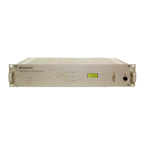
Page 40: Front Panel Description
Operational Date/Time Display Alarm State State Figure 4-4 Front Panel Description - example T1 Note: Rubidium is Stratum 2 OCXO is Stratum 3E OSA 5240 - User Manual - Revision P - June 2009... -
Page 41: Table 4-1 Operational / Alarm State- Osa 5240 R1.0E (E1 Model)
Time Code Operational Green Time Code Failure Time Code unsync. (---) (---) : Flashing (*) : OFF if not equipped Table 4-1 Operational / Alarm State– OSA 5240 r1.0E (E1 model) OSA 5240 - User Manual - Revision P - June 2009... -
Page 42: Table 4-2 Operational / Alarm State- Osa 5240 R1.1E (E1 Model)
Time Code unsync. (---) Power supply Power supplies failure (---) : Flashing (*) : OFF if not equipped Table 4-2 Operational / Alarm State– OSA 5240 r1.1E (E1 model) OSA 5240 - User Manual - Revision P - June 2009... -
Page 43: Table 4-3 Operational / Alarm State- Osa 5240 R1.0T (T1 Model)
- Minor alarm after 15 minutes in bridging mode - Major alarm and AIS after 24 hours in bridging mode Table 4-3 Operational / Alarm State– OSA 5240 r1.0T (T1 model) OSA 5240 - User Manual - Revision P - June 2009... -
Page 44: Table 4-4 Operational / Alarm State- Osa 5240 R1.1T (T1 Model)
- Minor alarm after 15 minutes in bridging mode - Major alarm and AIS after 24 hours in bridging mode Table 4-4 Operational / Alarm State– OSA 5240 r1.1T (T1 model) OSA 5240 - User Manual - Revision P - June 2009... -
Page 45: Rear Panel Layout
(wire-wrap adapter) Supply Voltage Input 1 (floating) Power 1 Screw Barrier Strip Supply Voltage Input 2(floating) Power 2 Screw Barrier Strip AC Ground DC Ground Table 4-5 Rear Connectors Description OSA 5240 - User Manual - Revision P - June 2009... -
Page 46: Outputs Slots - Osa 5240 R1.Xe (E1 Model)
In 8 Out 7 Out 8 Re-Timing Channels Out 1-4 In 1-4 SUB-D 8x E1 (2.048 Mbit/s) Re-timing channels (balanced) In 5-8 Out 5-8 Table 4-6 E1 Outputs slot 4-10 OSA 5240 - User Manual - Revision P - June 2009... -
Page 47: Outputs Slots - Osa 5240 R1.Xt (T1 Model)
Out 7 Out 8 - DS1 (1.544Mbit/s), balanced - 2.048MHz, unbalanced - 10MHZ, unbalanced - 1PPS, unbalanced Unbalanced → → Balanced SUB-9s, female Table 4-7 T1 Output slots 4-11 OSA 5240 - User Manual - Revision P - June 2009... - Page 48 OUT 7 OUT 8 8x outputs (OUT 1-8) with choice between: - DS1 (1.544Mbit/s), balanced - 2.048MHz, unbalanced - 10MHZ, unbalanced - 1PPS, unbalanced Unbalanced→ Balanced → Wire-wrap 3p 4-12 OSA 5240 - User Manual - Revision P - June 2009...
-
Page 49: Installation
Installation Chapter Installation Including : Unpacking and Inspection Working Conditions Tools Required Power-Up Connecting the GPS Antenna Connecting the Auxiliary Input Reference Connecting the Output Signals Time Code Output OSA 5240 - User Manual - Revision P - June 2009... - Page 50 Installation This page has been intentionally left blank OSA 5240 - User Manual - Revision P - June 2009...
-
Page 51: Unpacking And Inspection
Installation This section provides unpacking and Inspection instructions, working conditions, tools required and power up for the OSA 5240. To prevent injury and/or equipped damage, do not ignore the warnings, notes and recommendations and read the section 1.3Safety Instructions Note: If you encounter problems during any of the following procedures, please contact Customer Services. -
Page 52: Working Conditions
Installation Working Conditions In order to work within specification, the OSA 5240 Telecom GPS Receiver should be installed at a location which does not exceed the following working conditions: Operating temperature range : -5°C to +55°C Humidity : 5 to 95% non condensing... -
Page 53: Power-Up
Installation Power-Up CAUTION To avoid damage to the OSA 5240, access covers must not be removed except by trained service personnel. CAUTION For continued protection against risk of fire, ensure that only the specified fuse type and rating are used. Fuse specifications are contained in this section. -
Page 54: Connections
Installation 5.4.1 Connections The OSA 5240 Telecom GPS Receiver features two independent power inputs. Depending on the type, the unit is equipped according to one of the following specifications (refer to the rear panel indications): Input Type Voltage Range Fuse “IEC”... -
Page 55: Figure 5-3 Dc Connection View
CAUTION The minimum conductor size of the power cord for DC must be AWG 16. The Voltage Distribution fuse for the OSA 5240 MUST BE a fuse 4 AT/Time-lagT (low breaking). Ensure that only the specified fuse type and rating are used. Refer to the Information section. -
Page 56: Warm-Up
The AUX port should be disabled if unused. Do not loop connect any output to the AUX input. Power Consumption : 50 W (maximum, peaking during warm-up) depending on internal configuration. OSA 5240 - User Manual - Revision P - June 2009... -
Page 57: Connecting The Gps Antenna
(to power the Antenna and any amplifiers in the coaxial line) Recommendation: Prior to commissioning the main functions of the OSA 5240 Telecom GPS Receiver, it is necessary to check that the unit receives a clean signal from the satellite system and that the timing signal is valid. -
Page 58: Connecting The Auxiliary Input Reference
Auxiliary Input (Unbalanced option) Figure 5-6 Rear Unit Connection AUX Inputs Location Note: Please contact Oscilloquartz for further optional configurations and recommendations to meet your needs. 5-10 OSA 5240 - User Manual - Revision P - June 2009... -
Page 59: Figure 5-7 Bnc Aux Input Connector
In the case where an input reference signal must be derived from a G.703-6 or a G703-2 traffic carrying signal, insert an OSA TEX-P Passive Timing Extractor (part no. 942.089.035/036/037) and connect it to the OSA 5240 Telecom GPS Receiver as described in the TEX-P Operating Manual. -
Page 60: Timing Extractor - Passive (Tex-P)
Table 5-3 AUX Input Connectors - Sub-D, Wire-wrap 5.6.2 Timing Extractor – Passive (TEX-P) Signals from BRIDGED E1 / DS1 links can be connected to the OSA 5240 Telecom GPS Receiver using an external TEX-P. The TEX-P is a "Passive Line Bridging"... -
Page 61: Connecting The Output Signals
Installation Connecting the Output Signals Depending on the configuration of the OSA 5240 Telecom GPS Receiver, there are up to 16 outputs (two Output Groups with 8 outputs each) available for synchronizing telecommunication equipment. These need to be connected in accordance with the user’s network plan and/or wiring schedules. -
Page 62: Output Connectors Pin-Out
Table 5-4 Sub-D Output connectors 5.7.2.2 Wire-wrap (2p) Output Connectors This type of connector provides unbalanced connection with the following pin-out: Pin No. Signal Signal Shield Table 5-5 Wire-Wrap (2p) Output Connectors 5-14 OSA 5240 - User Manual - Revision P - June 2009... -
Page 63: Figure 5-10 Bnc Output Connectors
T (Tip) S (Shield) Table 5-7 Wire-Wrap (3p) Output connectors 5.7.2.5 BNC Output Connectors Pin No. Signal Ground Output Table 5-8 BNC Output connections Figure 5-10 BNC Output Connectors 5-15 OSA 5240 - User Manual - Revision P - June 2009... -
Page 64: Time Code Output
Ethernet timing Alarm Contact Output Wire Wrap Adapter The OSA 5240 Telecom GPS Receiver provides 3 alarm contacts for Critical, Major, and Minor Alarms. A DB15 to Wire Wrap Adapter can be affixed permanently to the rear panel DB15 Alarm connector. -
Page 65: Configuring The Unit
Configuring the Unit Chapter Configuring the Unit Including : Factory Default Parameters Configuration OSA 5240 - User Manual - Revision P - June 2009... - Page 66 Configuring the Unit This page has been intentionally left blank OSA 5240 - User Manual - Revision P - June 2009...
-
Page 67: Table 6-1 Factory Default Parameters
The cable delay depends on the type of the cable ordered and delivered with the unit. i.e. for our generic LMR-400 cable characteristics, please refer to the GPS Installation Guide OSA 5240 - User Manual - Revision P - June 2009... -
Page 68: Configuration
7.3 of this manual for pin-out and NULL Modem cable descriptions. Use the Local Manager software and user guide instructions to configure the OSA 5240 Telecom GPS Receiver. The following main parameters need to be set: •... -
Page 69: Remote Operations
Remote Operations Chapter Remote Operations Including : Features Electrical Alarm Outputs Local Management Capabilities Network Management Capabilities OSA 5240 - User Manual - Revision P - June 2009... - Page 70 Remote Operations This page has been intentionally left blank OSA 5240 - User Manual - Revision P - June 2009...
-
Page 71: Features
Network Management via a dedicated Management port (Ethernet). Electrical Alarm Outputs The OSA 5240 GPS displays an alarm summary on the front panel and also produces the associated electrical outputs for remote alarm monitoring. These electrical alarms are issued from relay isolated contacts and are available on the 'ALARM OUTPUTS' connector. -
Page 72: Wire-Wrap Adapter
The OSA 5240 Telecom GPS Receiver can be managed: • Locally, by connecting the OSA 5240 to an IBM-compatible PC loaded with the Local Manager for 5240 software application. Connection is made using an AT- LINK NULL MODEM cable from the 'RS-232C' port on the connector panel to the PC. -
Page 73: Rs-232C" Pin-Out
Table 7-2 RS232 for Local Management Pinout 7.3.1.1 NULL MODEM cable Pin-out DB9 (side 1) DB9 (side 2) Name Pin N° Name Pin N° DSR+CD 6+1 DSR+CD 6+1 Table 7-3 NULL MODEM cable OSA 5240 - User Manual - Revision P - June 2009... -
Page 74: Network Management Capabilities
Remote Operations Network Management Capabilities To facilitate this, the OSA 5240 Telecom GPS Receiver provides the following facilities: • A management port "REMOTE MGMT ", used to communicate with the managed equipment via a Data Communication Network 'DCN' (Ethernet). With this configuration, the following functions can be performed: •... -
Page 75: Maintenance & Troubleshooting
Maintenance & Troubleshooting Chapter Maintenance & Troubleshooting Including : Preventive Maintenance Checking the functional status of the OSA 5240 Telecom GPS Receiver Troubleshooting OSA 5240 - User Manual - Revision P - June 2009... - Page 76 Maintenance & Troubleshooting This page has been intentionally left blank OSA 5240 - User Manual - Revision P - June 2009...
- Page 77 If you encounter problems during any of the following procedures, contact our Customer Services. Keep the unit’s original packaging for re-shipping the product. If the original packaging has been discarded, contact the Customer Services Department for assistance. OSA 5240 - User Manual - Revision P - June 2009...
-
Page 78: Preventive Maintenance
5240 Telecom GPS Receiver MGMT 2003-12-16 FUSE RT/OUT B LOC 18:16:20 T3.15A L 250V (UTC +01:00) CRITICAL TIME CODE MAJOR MINOR RS-232 Management Port Figure 8-1 Remote Management Port OSA 5240 - User Manual - Revision P - June 2009... -
Page 79: Troubleshooting
Moisture; Waterproof and ANTENNA LED RED dry connections 4. Near Obstruction of Sky View; ANTENNA OUTAGE ANTENNA VIEW OBSTRUCTION remove obstruction or move Antenna ANTENNA LED RED mast location; see manual OSA 5240 - User Manual - Revision P - June 2009... - Page 80 TIMING ENGINE LED OSCILLATOR FAST TRACKING WARM UP and BRIDGING stages; RED FLASHING CHECK LOCAL MANAGER® (LM) SOFTWARE /TL1 SYNCTERM® INTERFACE ALARM LIST, Investigate prolonged or frequent flashing activity OSA 5240 - User Manual - Revision P - June 2009...
- Page 81 INTERFACE for DETAILS under format, Any of two PORT ALARM CODE #72 for incorrect configuration; capture RT/OUT LED RED [non Service Affecting] ALARM LIST information and EVENT HISTORY for OSA-CSS Agent analysis OSA 5240 - User Manual - Revision P - June 2009...
- Page 82 4. Check TIME CODE Ethernet patch FOR PROLONGED connections at both 5240 and PERIODS SERVICE TCU PATCH CONNECTIONS Hub/Switch/Router/Concentrator ports; AFFECTED/OUTAGES PING the TCU IP address ; correct as REPORTED necessary OSA 5240 - User Manual - Revision P - June 2009...
- Page 83 SYNCTERM (serial) TO across routed link and refresh local SETTING REAR ETHERNET Router Access Control List if necessary. MANAGEMENT PORT 5240 does NOT use DHCP; IP's must be set STATICALLY OSA 5240 - User Manual - Revision P - June 2009...
-
Page 84: Table 8-1 Troubleshooting
Table 8-1 Troubleshooting Recommendation: Contact your local representative, or the OSCILLOQUARTZ Oscilloquartz Customer Support Service for any service inquiries and advice on Timing issues and inquiries. 8-10 OSA 5240 - User Manual - Revision P - June 2009... -
Page 85: Oscilloquartz Contact Information
Fax: +41-32-722-5578 e-mail: css@oscilloquartz.com 8.4.1.2 North America Oscilloquartz USA Customer Support & Services 5475 Mark Dabling Boulevard, Suite 200 Colorado Springs, CO 80918-3848 Tel: +1-719-264-1777 Fax: +1-719-264-1911 e-mail: osausa@oscilloquartz.com 8-11 OSA 5240 - User Manual - Revision P - June 2009... -
Page 86: Sales
Fax: +41-32-722-5556 e-mail: osa@oscilloquartz.com 8.4.2.2 North America Oscilloquartz USA Sales & Marketing 5475 Mark Dabling Boulevard, Suite 200 Colorado Springs, CO 80918-3848 Tel: +1-719-264-1777 Fax: +1-719-264-1911 e-mail: osausa@oscilloquartz.com 8-12 OSA 5240 - User Manual - Revision P - June 2009... -
Page 87: Specifications
Specifications Chapter Specifications Including : Input Specifications Tracking Subsystem Characteristics Output Specifications - OSA 5240 r1.xE Output Specifications - OSA 5240 r1.xT Time Code Outputs Remote Functions General Specifications OSA 5240 - User Manual - Revision P - June 2009... - Page 88 Specifications This page has been intentionally left blank OSA 5240 - User Manual - Revision P - June 2009...
-
Page 89: Input Specifications
Input Validation See paragraph on Input Characteristics. Phase build-out function cancels phase offsets when switched from Max. Output Phase Change GPS to AUX. after Input Changeover Table 9-1 Input specifications OSA 5240 - User Manual - Revision P - June 2009... -
Page 90: Tracking Subsystem Characteristics
None required None required In-service adjustments > 50 years Life time > 15 years (3 x 10 pull in / 5 x 10 /month Table 9-2 Tracking SubSystem Characteristics OSA 5240 - User Manual - Revision P - June 2009... -
Page 91: Output Specifications - Osa 5240 R1.Xe
Specifications Output Specifications - OSA 5240 r1.xE The OSA 5240 Telecom GPS Receiver can be equipped to provide MAIN OUTPUTS the following capacity of outputs: up to 2 groups of 8 individually configurable outputs (between E1, 2.048MHz , 1PPS and 10MHZ),... -
Page 92: Output Specifications - Osa 5240 R1.Xt
Specifications Output Specifications - OSA 5240 r1.xT The OSA 5240 Telecom GPS Receiver can be equipped to provide MAIN OUTPUTS the following capacity of a choice of any two groups of outputs: up to 2 groups of 8 individually configurable outputs (between 2.048MHz , 1PPS and 10MHZ),... -
Page 93: Time Code Outputs
(adaptator on ‘TIME CODE’ Port, D-type 9p female) Detection of the following criteria causes Alarm detection: Output Qualification - Loss of Output Signal (AL) Table 9-5 Time Code Output Specifications OSA 5240 - User Manual - Revision P - June 2009... -
Page 94: Remote Functions
& remote management port to be presented in the management software. Non-volatile memory stores 128 events with date and time Event Log stamp on a FIFO (First in First Out) basis. Table 9-6 Remote Functions Specifications OSA 5240 - User Manual - Revision P - June 2009... -
Page 95: General Specifications
19" 2U: 88 (3.5’’) x 483 (19’’) x 331 (13’’) mm (with protection h x w x d mm (in.) shield) ~ 7 kg (16 lbs) excluding packing. Weight Rear access. Connector Access Table 9-7 General Specifications OSA 5240 - User Manual - Revision P - June 2009... - Page 96 Specifications This page has been intentionally left blank 9-10 OSA 5240 - User Manual - Revision P - June 2009...
-
Page 97: Appendix A : Ordering Information
Appendix A: Ordering Information The OSA 5240 is not field configurable. Internal Cards are fixed and cannot be interchanged when the shelf is installed on a rack. There are no internal field-replaceable components. The shelves are constructed to a fixed order and shipped for field installation. Therefore, only accessories can be ordered as spare or replaceable parts. -
Page 98: Table 9-9 Ordering T1 Units
Front Panel 0034.3122 A009010 FST 5x20 2A input/time-lag T Inside Connector 0034.3120 A009008 Table 9-10 Fuse Ordering Numbers Note: For further information on fuses, please check this link: http://www.schurter.com OSA 5240 - User Manual - Revision P - June 2009... -
Page 99: Table 9-11 Ordering Miscellaneous Accessories
Passive Timing Extraction Module A006144 942.089.035 Power Supply AC/DC (90-264VAC - 48VDC) A013943 930.200.007 120/75 ohms Balun A005318 938.752.011 75/50 ohms Adaptor A005317 938.705.011 Table 9-11 Ordering Miscellaneous Accessories OSA 5240 - User Manual - Revision P - June 2009... - Page 100 Ordering Information This page has been intentionally left blank OSA 5240 - User Manual - Revision P - June 2009...
-
Page 101: Glossary
Offset of phase-time between two signals in function of time, expressed in seconds Crystal Oscillator Phase-time difference at the input of the digital PLL filter (PI controller) y(t) Fractional frequency offset, normalized instantaneous offset from a reference, in function of time. OSA 5240 - User Manual - Revision P - June 2009... - Page 102 Glossary This page has been intentionally left blank OSA 5240 - User Manual - Revision P - June 2009...
-
Page 103: Index
Recommendations, defined, 1-4 Re-Timing Channel, 3-9 Input specifications, inspection, receiving, 5-3 Installation, 5-1 setting unit, 7-4 IRIG-B outputs, 3-10 shipping, procedure, 8-3 IRIG-B timing generation, 5-16 SSM mode, 3-7 OSA 5240 - User Manual - Revision P - June 2009... - Page 104 6-3 Syncview, 7-6 unit placement and exposure, 5-4 System architecture, 3-3 unpacking instructions, 5-3 Telecordia recommendation, ventilation, 1-6 tools required, 5-4 Tracking SubSystem Characteristics, Warranty, 1-8 working conditions, 5-4 OSA 5240 - User Manual - Revision P - June 2009...
-
Page 105: Document History
- Update alarm state in table 4-x - Update power consumption - Update fuse indication for EN and IEC standards - Add dimensional views - Add spares parts ordering section - Add antenna drawings OSA 5240 - User Manual - Revision P - June 2009... - Page 106 - Add Optical Fiber GPS antenna 10.03.2008 - Extract GPS Antenna Installation chapter - Update Oscilloquartz Service Contact link - Update ordering table 23.06.2009 - Correct IRIG-B carde codes OSA 5240 - User Manual - Revision P - June 2009...
Need help?
Do you have a question about the OSA 5240 and is the answer not in the manual?
Questions and answers