
Related Manuals for Fidelity Measurement CSa

Summary of Contents for Fidelity Measurement CSa
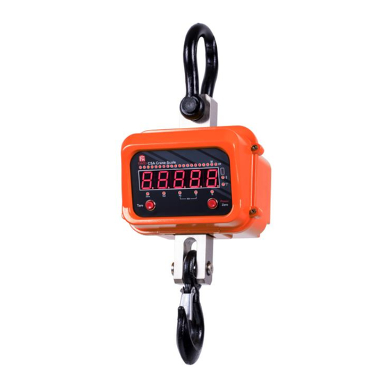
- Page 1 Advance Wireless Crane Scale Operation Manual (Full Version) PLEASE READ THIS MANUAL VERY CAREFULLY BEFORE OPERATING THIS INSTRUMENT Specifications subject to change without prior notice V100 Feb 2018...
-
Page 3: Table Of Contents
Content Content ....................... 3 1. Installation ...................... 7 Cautions ......................7 1.1 Metrological Legislation ................7 1.2 Seal & Serial Number ................7 1.3 Warm Up Time ..................7 1.4 Unpacking ....................8 1.5 Securing the Scale ................... 8 1.6 Support & Service ..................8 2. - Page 4 6.1 Power On / Off Instrument ..............20 6.2 Power On Countdown Sequence & Inputting Operator Number ... 20 6.3 Set Weight to Zero when Unloaded ............20 6.4 Tare Modes .................... 20 6.4.1 Manual Tare ..................20 6.4.2 Auto & Continuous Tare (F12) ............21 6.4.3 Manual Repetitive Tare (F13) ............
- Page 5 11. Customer & Product Code ................. 33 11.1 Enter a Customer & Product Code Manually ........34 11.2 Enter a Customer & Product Code by Scanner ........35 11.3 Clear a Customer & Product Code Entered ......... 35 11.4 Print a Customer & Product Code Entered .......... 35 12.
- Page 6 16.3 Battery Charging Status ............... 49 17. Error Codes ....................50 18. Daily Care & Maintenance ................. 51 19. Downloading Appendix A to E ..............51 Appendix A: - Keyboard Commands ..............52 Appendix B: - PC Output Protocols ..............53 Appendix C: - Operation Result Commands ............
-
Page 7: Installation
1. Installation Cautions a. Dangerous! Do not perform overhead weighing / operation with this instrument. Always stand clear of this instrument and weighed subject during weighing operation. b. Do not overload this instrument. c. The instrument is not an explosion proof device. d. -
Page 8: Unpacking
1.4 Unpacking Unpack this instrument very carefully. Check and make sure that the following items are included: - a. This operation manual x 1 b. Crane scale x 1 c. Battery Charger x 1 d. Infrared Remote Controller x 1 Contract your dealer if any items are missed. -
Page 9: Specifications
2. Specifications... -
Page 10: Keys, Display & Connection Points
3. Keys, Display & Connection Points... -
Page 11: Keys & Display On Instrument
3.1 Keys & Display on Instrument Name Description Capacity Bar To show applied and remaining capacity. M+ Indicator Visible when memory contains of accumulated data. IR Indicator Visible when receiving IR signal. IR Window Window for IR signal. Do not obstruct. Bluetooth Visible when Bluetooth is turned on. -
Page 12: Keys & Display On Remote Controller
3.2 Keys & Display on Remote Controller Name Description [Tare] Press this key to tare off the weight of a container. [MR] Press this key to recall total stored transactions. [Func] Press this key to shift between weighing, peak hold, animal weighing and PCd mode. -
Page 13: Power & Battery Recharging
4. Power & Battery Recharging This instrument comes with a built-in rechargeable battery and external rechargeable battery. 4.1 Power Adaptor Always use the power adaptor supplied together with this instrument to recharge the built-in and external rechargeable battery and to avoid un-recoverable damages to this instrument. -
Page 14: Ir Remote Controller Key Function Under Internal Function Mode
5.3 IR Remote Controller Key Function under Internal Function Mode Function in Setup & Calibration [Zero] Quit without saving. • Set F1 value being shown to zero and to display the net span gain of additional load applied. [Tare] • Fast forward during Customer / Product code data input. -
Page 15: Internal Function Table
5.4 Internal Function Table Refer to the below tables for internal function number, parameter and setting notes. Functi Parameters / Note Description Default = ** Press [Print/M+] to set offset value to zero when unloaded. Then add load to observe the net span value of the load applied. - Page 16 If YES is selected, scale displays “SURE ?” for confirmation. At this point: - • Press [Set] to confirm, or • Press any other key to quit. Scale shows Done when initialization is completed. Auto Power Off Time ** 5 (Minute) Brightness ** 4...
- Page 17 • OFF = Comport disable. • Auto1 = auto print when weight is stable. • Auto2 = the highest stable weight value (of a weighing process) will be automatically printed when all loads are removed (and gross weight returns to zero or minus). •...
-
Page 18: Weight Unit Conversion
during operation status. Lab 2 Weight Function ** STD CUSTO Output Print Format Lab 2 Animal Functions Output Print ** STD CUSTO Format Ask for Operator No. ** No (Disable) YES (Enable) During Startup Read Calibration and Parameter set counts. •... -
Page 19: Auxiliary Function Modes
Indicator appears, then press [Print/M+] to confirm and go to next weight unit setting. • To enable/disable weight unit Newton (Kilo Newton):- Select On/Off when Newton/Stable Indicator appears, then press [Print/M+] to confirm. 5.6 Auxiliary Function Modes This instrument supports below 3 auxiliary function modes: - ... -
Page 20: Basic Operations
6. Basic Operations 6.1 Power On / Off Instrument To power on, press [Power/Zero] on instrument. To power off, press and hold [Power/Zero] on instrument for 1 second4, or press [Off] once on remote controller. 6.2 Power On Countdown Sequence & Inputting Operator Number After powered on, instrument will display: - a. -
Page 21: Auto & Continuous Tare (F12)
Weight displayed will become zero and Net Indicator appears to indicator tare is in effect and weight being displayed is net weight. To cancel tare effect, remove all loads and press [Tare]. Net Indicator disappears. 6.4.2 Auto & Continuous Tare (F12) 3 parameters are available: - Off, Auto and Contin ... -
Page 22: Select The Preferred Function Mode
indicate the value being displays is net weight. To cancel preset tare effect, enter a zero preset tare value then press [Print/M+]. Note: - Manual tare is possible when Repetitive Tare (F13) is set to ON. 6.5 Select the Preferred Function Mode To utilize the preferred function mode, press [Func] until the abbreviation of the desired function mode appears then press [Print/M+] to enter. -
Page 23: Automatic Accumulation
6.7.1 Automatic Accumulation Automatically accumulation is activated when Auto Accumulation is set to On in Auto 1, Auto 2, Auto 3 or Manual mode is selected in F16 and/or F17. Under the automatic accumulation mode, corresponding results will be accumulated automatically. 6.7.2 Manual Accumulation Manual Accumulation is activated when scanner, PC or CMD mode is selected for both F16 and/or F17. -
Page 24: Weighing Mode
transactions accumulated) and total accumulated result. At this point: - • Press [Zero] to quit, or • Press [MC] to clear memory. After [MC] is pressed, instrument display Clear and M+ Indicator disappears to indicate all no data is stored in memory. 7. -
Page 25: Peak Hold Mode
8. Peak Hold Mode Under this mode, the instrument will display and hold the highest load/force detected. Refer to 5.5 on how to select the desired weight unit. Refer to 5.6 on how to enter Peak Hold mode. Complete all necessary test setup. If mounting/support accessories are used, apply all of them. -
Page 26: Start Using Animal Weighing
• rE 20 = auto release when weight varies ≥20% of rate capacity. Press [Print/M+] to save. Instrument is now ready for animal weighing application. 9.3 Start using Animal Weighing Lift animal. This instrument will calculate the weight of an animal. The result obtained will be flashing. -
Page 27: Default Settings Of Built-In Wifi Module
Contact your dealer for other details. 10.2 Default Settings of Built-in WIFI Module • SSID = USR-WIFI232-T • Protocol = TCP-Server • Port ID = 8899 Contact your dealer for other details. 10.3 Comport Setting Procedures Following the below procedures to setup comports. a. -
Page 28: When Comport Is Set As Pc
• If Scanner is selected, refer to 10.3.5 for setting details. 10.3.1 When comport is set as PC 1. Instrument displays baud rate. 9 parameters (1200~256000) are available. Press [Func] or [Unit] until the preferred parameter appears then press [Print/M+] to save. 2. -
Page 29: When Comport Is Set As Manual
will be employed by default. 4. At this point, CMD setup is completed. 10.3.3 When comport is set as Manual Instrument displays baud rate. 9 parameters (1200~256000) are available. Press [Func] or [Unit] until the preferred parameter appears then press [Print/M+] to save. Instrument displays Parity. - Page 30 Instrument displays print format. 7 parameters (Lab 1, Lab 2, Lab 3, Lab 4, Lab 5, LP-50 and TSC). Press [Func] or [Unit] until the preferred parameter appears then press [Print/M+] to save. • Lab 1 = Output in Landscape direction. If Lab 1 is selected, refer to 10.3.3.1 for other settings.
-
Page 31: When Comport Is Set As Auto (Auto 1~3)
10.3.3.3 Other settings if Lab 4 / Lab 5 is selected 1. Instrument displays current statistic data output (Sd) setting (On / Off). When Sd is set to On, the below statistical results will also be transmitted. • Max = Maximum Value •... - Page 32 Press [Func] or [Unit] until the preferred parameter appears then press [Print/M+] to save. Note: - baud rate, parity and data length settings will be bypassed when Bluetooth or WIFI is enabled in F38. If it is the case, baud rate 115200 will be employed by default.
-
Page 33: When Comport 1 Is Set As Scanner
10.3.5 When Comport 1 is set as Scanner Instrument displays baud rate. 9 parameters (1200~256000) are available. Press [Func] or [Unit] until the preferred parameter appears then [Print/M+] to save. Instrument displays Parity. 3 parameters (None, odd, even) are available. Press [Func] or [Unit] until the preferred parameter appears then press [Print/M+] to save. -
Page 34: Enter A Customer & Product Code Manually
11.1 Enter a Customer & Product Code Manually 1. Go to customer/product code setting manual by either one of the below method. • If Quick Manual Code Entry function (PCd) in F11 is set to on: - Press [Func] until C.P. Cod appears then press [Print/M+]. Press [Func] or [Unit] until the desired mode appears ... -
Page 35: Enter A Customer & Product Code By Scanner
11.2 Enter a Customer & Product Code by Scanner Default scanner input target is product code. To change scanner input target, scan either one of the below barcodes, then scan a customer or product barcode. 11.3 Clear a Customer & Product Code Entered To clear a customer/product code entered, press [Hold] for procedures 2 paragraph 11.1, the press [Print/M+]. -
Page 36: Enter A Key Command By Scanner
12. Enter a Key Command by Scanner Simply scan one of the below barcodes to simulate pressing the [Zero], [Tare] and [Print/M+] on keyboard. Simply scan one of the below barcodes to simulate pressing the [Zero], [Tare] and [Print/M+] on keyboard. 13. -
Page 37: Requesting Operation Results & System Parameters By Computer
13.3 Requesting Operation Results & System Parameters by Computer To obtain operation results and system parameters by computer, set F17 to CMD. • Refer to Appendix C for details to obtain operation results. • Refer to Appendix D for details to obtain system parameters. 14. -
Page 38: Standard Lab 2 Print Format
14.2 Standard Lab 2 Print Format Standard ticket/receipt printout of various function modes are described illustrated below. Refer to below diagram for printout content. When Lab 2 is selected under in F16 and/or F17... -
Page 39: Customizing Lab 2 Print Format
14.3 Customizing Lab 2 Print Format Custom printout is available for the below modes: - • Weighing. • Animal weighing. 19 variants + 2 commands (Cr LF and End) are available for custom print output format. Refer to the below Print output format variants table for more detail. 14.3.1 Print output format variants table Symbol Description... -
Page 40: To Edit Custom Lab 2 Print Output Format
14.3.2 To edit custom Lab 2 print output format Follow the below steps to create custom printout. a. Go to internal function and select the desired function number to edit, b. Select CUSTOM and press [Print/M+], c. This instrument displays Line 1 and the last variant or command (see 14.3.1 for details) stored, d. -
Page 41: Lab 3 Data Base Output Format
14.4 Lab 3 Data Base Output Format Current working mode and all related data are sent under this mode. Refer to below table for data output format. Note: - Semi colon is inserted between data. When Lab 3 is selected under in F16 and/or F17... -
Page 42: Lab 4 Print Format
14.5 Lab 4 Print Format Transaction data is sent in journal output format with gross and net weight of each individual transaction. Refer to below diagram for details. When Lab 4 is selected under in F16 and/or F17... -
Page 43: Lab 5 Print Format
14.6 Lab 5 Print Format Transaction data is sent in journal output format with time and net weight of each individual transaction. Refer to below diagram for details. When Lab 5 is selected under in F16 and/or F17... -
Page 44: Label Printing
15. Label Printing This instrument supports the below label printer models: - • LP50 by Datecs (www.datecs.bg/en) • TDP247, TDP345 by TSC (www.tscprinters.com) • TTP247, TTP345 by TSC (www.tscprinters.com) Notes: - • Set all preferred operation parameters according to F16 and/or F17 listed on 5.4. -
Page 45: Fl2 (Label Format Group 2)
• FL1 01: - Select this to print label file AA01 stored in printer. • FL1 02: - Select this to print label file AA02 stored in printer. • …. • FL1 98: - Select this to print label file AA98 stored in printer. •... -
Page 46: Label Programing Information Table
15.2.1 Label programing information table Prompt Working Suggested Description Command Mode Length Peak Value Peak Product Code Machine ID Machine Group Number Operator Number Date Time No. of accumulated transaction (8 digits with leading space) No. of accumulated transaction (6 digits with leading zero) Total accumulated weight Total accumulated weight without unit or decimal... - Page 47 Gross weight without unit or decimal Animal Weight hold Weighing Weight hold without unit or Animal decimal Weighing Customer Code...
-
Page 48: Label Programming Sample
15.2.2 Label programming sample 15.2.2.1 Sample label of current transaction (FL1) 15.2.2.2 Sample label of totalized data (FL2) -
Page 49: Built-In Battery & Recharging
16. Built-in Battery & Recharging 16.1 Battery Operation Time Depends on the battery operation condition, a new and fully charged rechargeable battery can provide 40~60 operation hours depend of actual power consumption. The following settings help saving extra energy: - •... -
Page 50: Error Codes
17. Error Codes Error Description Code No. Err 1 Time value error Err 2 Date value error Err 3 Exceed manual zero Err 4 Offset out of range / unstable during power on Err 5 No load cell detected Err 6 Tare operation error Err 13 Exceed maximum power on... -
Page 51: Daily Care & Maintenance
--oL-- Overload (Gross weight is more than Max plus 9d) bAt.Lo Battery level low Major system error detected. Power off instrument and HALT remove power adaptor immediately. Then check load cell connection and system power status. UndEr Negative Weight values exceeds display range Important parameters have been changed. -
Page 52: Appendix A: - Keyboard Commands
Appendix A: - Keyboard Commands Keyboard commands can be sent to this instrument from computer through any standard communication program to simulate keyboard entries. To enable keyboard commands, connect the external peripheral which generates keyboard commands to Comport 2 and set Comport 2 to CMD. Keyboard Command format as below: - a. -
Page 53: Appendix B: - Pc Output Protocols
Appendix B: - PC Output Protocols... -
Page 57: Appendix C: - Operation Result Commands
Appendix C: - Operation Result Commands Operation Result commands are those commands which are used to request operation result and details from this instrument. These commands can be sent to this instrument from computer through any standard communication program. Command format as below: - a. - Page 58 No. of accumulated transaction Total accumulated weight Total accumulated weight without unit or decimal Net weight Net weight without unit or decimal Tare weight Tare weight without unit or decimal Gross weight Gross weight without unit or decimal HI limit LO limit Comparison Result Number of piece...
-
Page 59: Appendix D: - System Parameter Inquiry Commands
Appendix D: - System Parameter Inquiry Commands System parameter inquiry commands are used to check system parameter settings. Command format as below: - a. Hex code 0D (ASCII code $0D), then b. Hex code 0A (LF) (ASCII code $0A), then c. - Page 60 = lb: - 0 = no decimal; 1 = 1 decimal place…… 4 = 4 decimal place = capacity in kg. Data length = 8 including decimal with leading space (Hex code 20) = capacity = g. Data Capacity1 of kg, g, length = 8 including decimal with leading space...
- Page 61 = lb: - 0 = 1; 1 = 2; 2 = 5; 3 = 10; 4 = 20; 5 = 50 = kg: - 0 = 1; 1 = 2; 2 = 5; 3 = 10; 4 = 20; 5 = 50 Division 2 of kg, g, ...
- Page 62 = weight value of LD2. Data length = 8 including decimal with leading space (Hex code 20). = ad value of LD2. Data length = 8 (integers only) with leading space (Hex code 20). = as value of zero point. Data length = 8 (integers only) with leading space (Hex code 20).
- Page 63 = auto zero tracking speed: - 00 = Off; 01 = 0.25e; 02 = 0.50e; 03 = 10e; 04 = 1.5e; 05 = 2.0e; 06 = 2.5e; 07 = 3.0e; ….; 09 = 5e; 10 = 7.5e; 11 = ...
- Page 64 weighing, low limit = near zero value. Data for weighing, high length = 8 with leading limit for counting, space (Hex code 20) low limit for counting = Hi Limit for weighing. Integer only. Data length = 8 including decimal with leading space (Hex code 20).
- Page 65 data length, parity, = print stability control: - minimum output 0 = no (disable); 1 = Yes weight value (enable) = transmission interval: - 0 = int 0; 1 = int 0.5; 2 = int 1.0; 3 = int 1.5; ….; 9 = int 300.
- Page 66 = from 20d. Data length = 2 with leading zero = working mode: - 0 = Auto 1; 1 = Auto 2; 2 = Auto 3; 3 = Manual; 4 = PC; 5 = CMD; 6 = Off = baud rate: - 0 = 1200;...
- Page 67 AA01; …98 = file AA98; 99 = file AA99 = label format group 2 file number (00~99): - 00 = file BB00; 1 = file BB01; …98 = file BB98; 99 = file BB99 = data length: - 0 = 7bit;...
-
Page 68: Appendix E: - Tsc Printer Installation & Setup Procedures
4-digit operator number. Operator Number **** = no operator number is set Appendix E: - TSC Printer Installation & Setup Procedures E.1 Before Installation Get the below ready before printer installation. An appropriate cable to connect printer and computer. This cable usually comes with the printer. -
Page 69: Uploading Tcf File To Printer
E.1.2 Uploading TCF File to Printer In order to allow proper operation between this instrument and TSC label printer, a TCF file must be uploaded to printer. Connect printer with computer. Power on printer. Download the correct TCF file point 4 of E.1. Unzip the download file and save in to... -
Page 70: Appendix F: - Create & Upload Label To Tsc Printer
Appendix F: - Create & Upload Label to TSC Printer F.1 Selecting the Correct Edition for Bartender Software To enable label uploading from computer to TSC printer, it is necessary to run as Bartender as Automation or Enterprise Automation edition. Procedures as below: - Install Bartender Software to computer. - Page 71 On Template Field, select Template Field for Type. Enter the correct label file name on Name/Value. Refer to 15.1 for correct file name format. (a) click Copies, check KDU and (b) input asterisk (*) on Prompt box. Below procedures explain how to edit information to be obtained from instrument.
- Page 72 Fidelity Measurement Co., Ltd. www.fi-measurement.com e-mail: info@fi-measurement.com...
Need help?
Do you have a question about the CSa and is the answer not in the manual?
Questions and answers