
Summary of Contents for Fidelity Measurement AFM18
- Page 1 AFM18 / FM18 / FM18S ELECTRONIC WEIGHING INDICATOR OPERATION MANUAL PLEASE READ THIS MANUAL VERY CAREFULLY BEFORE ATTEMPT TO OPERATE THIS INSTRUMENT Specifications subject to change without prior notice V118 December 2015 Rev1...
- Page 2 www.fi-measurement.com...
-
Page 3: Table Of Contents
Content 1. Installation ...................... 5 2. Specifications ....................6 3. Keys, Display & Connections ................. 7 3.1 Keys & Display Indicators ................. 7 3.2 Connection Points .................. 11 4. Getting Started ..................... 13 4.1 Built-In Rechargeable Battery..............13 4.2 Power Adaptor ..................13 4.3 Connecting Other Devices.............. - Page 4 6.5.1 To Accumulate a Transaction to Memory ........28 6.5.2 Memory Recall and Clearance ............28 6.6 Function Modes ..................29 6.7 To Enter & Quit from Supplementary Function Mode ......29 6.7.1 To Enter a Function Mode ..............29 6.7.2 To Enter &...
- Page 5 6.16 Constant Dispensing Mode ..............46 6.16.1 Constant Dispensing Illustration System Block Diagram ....46 6.16.2 Constant Dispensing Sequence Diagram ........47 6.16.3 Constant Dispensing Sequence Description ......... 47 6.16.4 Auto Reservoir Refill Function ............49 6.16.5 Auto Reservoir Refill Sequence Description ........49 6.16.6 Constant Dispensing Auto Printout ..........
-
Page 6: Installation
1. Installation Because of metrological legislation, installation / some metrological parameter settings are limited to be done by authorized personnel only. Do not attempt to change any of the built-in parameters. Contact your dealer for installation and technical assistance. Caution: - This instrument is legal for trade only when it is sealed (and/or stamped) and bearing a serial number. -
Page 7: Specifications
2. Specifications Single Range Mode: - • Max = 1 ~ 999,999 (kg or lb) Dual Range Mode: - Maximum Capacity • = 1 ~ 999,998(kg or lb) • = 2 ~ 999,999(kg or lb) • < Max Condition = Max Single Range Mode: - •... -
Page 8: Keys, Display & Connections
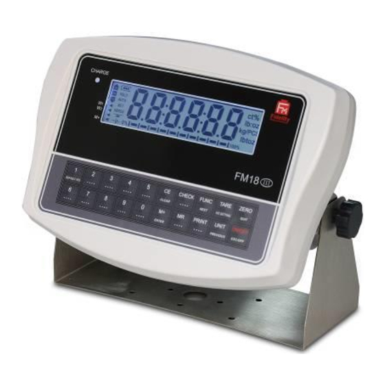
3. Keys, Display & Connections 3.1 Keys & Display Indicators 1. ON/OFF KEY Press this key to turn this instrument on or off. 2. UNIT KEY Press this key to shift among various weight units (if weight unit conversation is enabled). www.fi-measurement.com... - Page 9 3. PRINT KEY Press this key to print the results to a computer or a printer through the RS-232 output. 4. MR KEY Press this key to recall total stored transactions. 5. M+ KEY Press this key to accumulate current weight to memory manually. 6.
- Page 10 12. CHECK SYMBOLS • Hi = Weight reading is higher than the Hi limit entered, • OK = Weight reading is in between than the Lo and Hi limits entered, • Lo = Weight reading is lower than the Lo limit entered. 13.
- Page 11 20. NET INDICATOR Visible when the tare function is in effect. Weight reading shown is net value. 21. GROSS INDICATOR Visible when gross weight reading is displayed. 22. STABLE INDICATOR Visible when weight reading is stable. 23. ZERO INDICATOR Visible when instrument is at true zero weight status. 24.
-
Page 12: Connection Points
3.2 Connection Points AFM18 & FM18 FM18S www.fi-measurement.com... - Page 13 B. RESERVED C. LOAD CELL CONNECTOR (7-Pin) • AFM18 & FM18: - Signal wires from load cell (or junction box) are connected here. • FM18S: - Thread though signal cable from load cell (or junction box) here.
-
Page 14: Getting Started
4. Getting Started In order to obtain an accurate weighing result, the weighing platform must be placed on a strong and level surface. Avoid using the platform and this instrument in environment where excessive wind flow, vibration and extreme temperature change exist General Warnings: - •... -
Page 15: Connecting Other Devices
4.3 Connecting Other Devices 4.3.1 Connection with Weighing Platform (Load Cell) Connect this instrument with a weighing platform (load cell) through LOAD CELL CONNECTOR located at the back according to the below pin assignment table. If a 4-wire load cell or junction box is used, short-circuit pin 1 & 2 and pin 3 & 4. Otherwise, this instrument will not work. -
Page 16: Connecting Rs232 To Printer (Db25)
4.3.3 Connecting RS232 to Printer (DB25) RS232 COMPORT (DB9) ON COMPUTER COM DB25 INSTRUMENT 2 = RXD 3 = TXD 3 = TXD 2 = RXD 5 = GND 7 = GND 4.3.4 Connecting the Optional External Relay Output Module If the optional relay output module is purchased, simply plug in the DB-25 connector of the relay output module to the TTL &... -
Page 17: Connecting Devices By Others To Ttl Comport
4.3.7 Connecting Devices by Others to TTL Comport Follow the below TTL COMPORT PIN ASSIGNMENT TABLE for pin assignment. This instrument provides low-active TTL signals. Do not connect the wireless data communication port to any other non-TTL devices; this may cause unrecoverable damages to this instrument. - Page 18 Notes: - 1. F1~F26 are accessible without restriction, 2. F60~F66 are restricted functions, which may request a password or hardware key to access, 3. F80 ~ F99 are restricted functions, which may request a password or hardware key to access. These functions are usually for dealer and authorized personnel only and all settings these functions are monitored and recorded.
-
Page 19: Initial Setup
5. Initial Setup 5.1 Internal Settings Application parameters can be checked and set through internal functions. Refer to 5.4 for description of all internal functions. 5.2 How to Enter & Select Internal Function Follow the below steps to enter and select desired parameter of an internal function. -
Page 20: Internal Function Table
5.4 Internal Function Table www.fi-measurement.com... - Page 21 www.fi-measurement.com...
- Page 22 www.fi-measurement.com...
- Page 23 www.fi-measurement.com...
- Page 24 www.fi-measurement.com...
- Page 25 www.fi-measurement.com...
-
Page 26: Instruction For Use
6. Instruction for Use 6.1 Power On Power on this instrument, it will: - a. Display software number and revision (if any) b. Display the calibration count value, c. Display the parameter set count value, d. Display all display segments, e. -
Page 27: Units (F9)
6.3.2 Conversion between Metric (kg and/or g) and Imperial (lb) weight units (F9) This instrument supports conversion among kg, g and lb. To enable this conversion function, set F9 = ON. Press [UNIT] to shift among various weight units. The weight unit employed before power off will be employed when powered on again. -
Page 28: Repeated Tare (F13)
6.4.3 Repeated Tare (F13) When F13 is set to OFF, this instrument does not permit multiple tare operation. Tare effect can only be cancelled when container is removed and gross weight = zero. When F13 is set to ON, this instrument will permit multiple tare operation provided that both of the below requirements are met: - a. -
Page 29: Memory Accumulation Function
6.5 Memory Accumulation Function 11 12 13 6.5.1 To Accumulate a Transaction to Memory a. Press [M+] to save and accumulate data of current transaction to memory, b. This instrument displays “≡ n”. M+ INDICATOR appears to indicate that memory contains stored data. “≡ n” means the total number of transactions accumulated to memory, c. -
Page 30: Function Modes
6.6 Function Modes This instrument is equipped with the below function modes: - • Piece Count, • Percentage, • Animal weighing (When F11 = on), • Checkweighing (HI/LO check) for above functions. 6.7 To Enter & Quit from Supplementary Function Mode 6.7.1 To Enter a Function Mode Press [FUNC] to shift among Piece Count (CoUnt), Percentage (PErCnt), Animal weighing (Ani) modes and then press [M+] to enter when the desired... -
Page 31: Sampling Process
6.8.1 Sampling Process a. Put samples with same quantity on platform then press [M+]. Should a different sample size is required, enter the quantity of the sample size through the numeric keys b. Apply samples with the same quantity as being displayed on this instrument and press [M+], c. -
Page 32: Percentage Function
6.9 Percentage Function Follow the below steps to enter Percentage Function: - a. Refer to 6.3 on how to select the desired weight unit, b. If a container is used, place it onto the platform and press [TARE], c. If a reference mass (mass value which is considered as 100%) is available, apply it on platform, Note: - If reference mass is not available or reference mass value will be entered through numeric keys, then ignore this step. - Page 33 Function (Ani) appears, d. Press [M+] to enter, e. Display last error control (E) value applied. Select the preferred error control value by pressing [FUNC] or [UNIT] key, 5 error control values are available: - • E 2d = 2d, •...
-
Page 34: Weighing Animal
• rE 2 = auto release when weight varies ≥2% of rate capacity (or W1 for dual range), • rE 5 = auto release when weight varies ≥5% of rate capacity (or W1 for dual range), • rE 10 = auto release when weight varies ≥10% of rate capacity (or W1 for dual range), •... -
Page 35: Checkweighing Mode
30 31 32 6.11 Checkweighing Mode This instrument is equipped with various checkweighing modes. See F25 for check modes availability. 6.11.1 To Trigger Checkweighing Mode 1 and Mode 2 Follow the below steps to trigger checkweighing Mode 1 and Mode 2: - a. -
Page 36: Standard / Dynamic Checkweighing Mode (F25 = Mode 1)
6.12 Standard / Dynamic Checkweighing Mode (F25 = Mode 1 This mode is used to compare the weight reading obtained with the preset Hi and Lo limits set to this instrument. The comparison result (HI, OK or LO) will then be displayed with or without buzzer External control equipment can utilize the comparison result through the optional RELAY-4, 4-channel relay module. -
Page 37: About Near Zero Value (F26)
6.12.2 About Near Zero Value (F26) Nero zero value is useful for dynamic weighing applications when weight value is the checking target. It is used to avoid false LO signal output when load is approaching and leaving the weighing platform. HI/OK/LO comparison will only start when weight reading exceeds the pre-set near zero value. -
Page 38: Inflow/Outflow Control Logic Mode (F25 = Mode 2)
6.13 Inflow/Outflow Control Logic Mode (F25 = Mode 2) The inflow/outflow logic mode is built-in the software to simplify the control system. Refer to below diagram for more information of this control logic. 6.13.1 Diagram: - Inflow / Outflow This control logic should always be achieved through the optional Relay-4 4-Channel Relay Module. -
Page 39: Constant Feeding (F25 = Mode 3) & Dispensing (F25 = Mode 4) Modes
6.14 Constant Feeding (F25 = Mode 3) & Dispensing (F25 = Mode 4) Modes Constant feeding and dispensing control logics are built-in the software to support constant feeding and dispensing system. To utilize constant feeding function, select Mode 3 in internal function F25. To utilize constant dispensing function, select Mode 4 in internal function F25. - Page 40 which auto refill starts. • Condition: rEFl L < = rEF H • Set Point 1. • This is the weight value at or above which fast (Set Point 1) feeding/dispensing comes to end. • Condition: SP1 < = SP2. Set Point 2.
-
Page 41: Key Functions During Operation And Parameters Setting
be reached (Relay 4 starts action). SP3 is the preset alarm weight value. SP3, Delay 3 and Relay 4 together are used for fail safe proposes. 6.14.2 Key Functions during Operation and Parameters Setting Refer to the below table for Key functions during feeding / dispensing operation and parameters setting. -
Page 42: To Enter And Set Parameters For Mode 3 & Mode 4
• During operation: - To recall total number of stored [MR] transactions and total accumulated gross weight. • During parameter setting: - No function. • During operation: - Accumulate current weight to memory (if a net weight = zero or negative has been [M+] previously attained). -
Page 43: Constant Feeding Mode
(by UNIT Key) (Connected with reservoir refill start/stop) RELAY 2 SP1 Output. • To be connected with fast feeding valve / gate (Mode 3) • To be connected with fast dispensing valve / gate (Mode 4) RELAY 3 SP2 Output •... -
Page 44: Constant Feeding Sequence Diagram
6.15.2 Constant Feeding Sequence Diagram Refer to below illustration diagram for feeding sequence. 6.15.3 Constant Feeding Sequence Description Seq. Point Description In case [UNIT] key is pressed, or automatically triggered by Seq. 11 automatically ) Relay 1 starts action. [FUNC] key is pressed. Relay 1 stops action. - Page 45 Weight of container is tare off automatically Relay 2 (SP1) starts action. Fast feeding starts. Weight value of SP1 is reached. Relay 2 stops action. Fast feeding stops. Time delay as set forth in Delay 2. This is the stabilization waiting time before SP2 (slow feeding ) starts.
-
Page 46: Constant Feeding Auto Printout
Instrument displays gross weight (Tare weight + weight of material filled). 37 38 A printout is generated automatically. A signal is sent to trigger Relay1. 6.15.4 Constant Feeding Auto Printout After each successful feeding transaction, a printout of that transaction will be generated. -
Page 47: Constant Dispensing Mode
3. Weight of value (of the container) of this current feeding transaction has been tare off. 4. Gross weight of the container (after material has been filled in). 5. Total accumulated net weight of material fed. 6.16 Constant Dispensing Mode 6.16.1 Constant Dispensing Illustration System Block Diagram Marking Description... -
Page 48: Constant Dispensing Sequence Diagram
6.16.2 Constant Dispensing Sequence Diagram Refer to below illustration diagram for dispensing sequence. 6.16.3 Constant Dispensing Sequence Description Seq. Point Description [FUNC] key is pressed. Instrument displays Start. C D Time delay as set forth in Delay 1. Dispensing sequence starts. Relay 2 (SP1) starts action. - Page 49 automatically. Relay 3 (SP2) starts action. Slow dispensing starts. Weight value of SP2 is reached. Relay 3 stops action. Slow dispensing stops. Time delay as set forth in Delay 3. This is the stabilization / waiting time before the dispensing process is completed and automatically stopped.
-
Page 50: Auto Reservoir Refill Function
6.16.4 Auto Reservoir Refill Function The constant dispensing control logic comes with auto reservoir refill & output logic. Refer to below diagram illustration diagram for auto reservoir refill sequence. 6.16.5 Auto Reservoir Refill Sequence Description Seq. Point Description I Reservoir refill in process. -
Page 51: Constant Dispensing Auto Printout
Weight of material in reservoir drops below SP2 after the last dispensing sequence completed. [FUNC] pressed start another dispensing sequence. K L Time delay as set forth in Delay 1. Relay 1 starts action. Reservoir refill starts. I Reservoir refill in process. - Page 52 TIME 07:01:00 DATE 27.10.2010 (Note 1) 201kg (Note 2) TARE GROSS 615kg (Note 3) TOTAL 414kg (Note 4) Notes: - 1. (In case internal function F17 auto accumulation is set to on) sequence number (also = total number) of current dispensing transaction …etc.
-
Page 53: Rs232 Data Output Mode
7. RS232 Data Output Mode There are 3 data output modes available • Mode 1 and Mode 2 are for communication with computer and other peripherals which accept and process continuous data communication, • Mode 3 is for transmission to printer or other peripheral which accepts only single or manual data transmission. -
Page 54: Ticket / Receipt Printing
8. Ticket / Receipt Printing If a ticket/receipt printer is used, select Mode 3… normal should be selected in internal function F18. 46 47 8.1 Standard Print Output Format Standard ticket/receipt printout of various function modes are illustrated below. Press [PRINT] for manual output or set F17 = ON for automatic output. 8.1.1 Standard Output Print Format 8.1.1.1 Weighing function 7 lines will be transmitted as below: -... - Page 55 Sample 2 TIME 15:21:16 DATE 14.04.2009 (Second transaction added to memory) 200.0kg TARE 0.0kg GROSS 200.0kg TOTAL 700.0kg (Total accumulated net weight) Sample 3 TIME 15:21:25 DATE 14.04.2009 (Third transaction added to memory) 500.0kg TARE 200.0kg GROSS 700.0kg TOTAL 1200.0kg (Total accumulated net weight) 8.1.1.2 Piece count function 5 lines will be transmitted as below: -...
- Page 56 Sample 2 TIME 15:31:54 DATE 14.04.2009 500.0kg UNIT.W 599.949 g COUNT 833PCS 8.1.1.3 Percentage function 5 lines will be transmitted as below: - 1. Time of printing, 2. Date of printing, 3. Net weight, 4. Weight value of reference (100%) mass, 5.
-
Page 57: Standard Output Print Format Of Checkweighing Mode
8.1.2 Standard Output Print Format of Checkweighing Mode 8.1.2.1 Weighing function with checkweighing 12 lines will be transmitted as below: - 1. Time of printing, 2. Date of printing, 3. Transaction sequent number (if this transaction is accumulated to memory), 4. - Page 58 Sample 2 TIME 17:39:15 DATE 14.04.2009 500.0kg TARE 0.0kg GROSS 500.0kg TOTAL 4299.0kg HIGH 2000.0kg 500.0kg ACCEPT Sample 3 TIME 17:39:34 DATE 14.04.2009 2500.0kg TARE 200.0kg GROSS 2700.0kg TOTAL 6799.0kg HIGH 2000.0kg 500.0kg ABOVE LIMIT 8.1.2.2 Piece count function with checkweighing 10 lines will be transmitted as below: - 1.
- Page 59 6. One blank line, 7. One blank line, 8. Hi limit, 9. Lo limit, 10. Comparison result. Sample 1 TIME 17:48:07 DATE 14.04.2009 500.0kg UNIT.W 1001.04 g COUNT 499PCS HIGH 1000PCS 500PSS BELOW LIMIT 8.1.2.3 Percentage function with checkweighing 10 lines will be transmitted as below: - 1.
-
Page 60: Custom Print Output Format
Sample 1 TIME 17:51:09 DATE 14.04.2009 500.0kg REF % 200.0kg PERCENT 250.00kg HIGH 1500.0 % 750.0 % ABOVE LIMIT 49 50 8.2 Custom Print Output Format Maximum 10 or 15 lines can be included for the below functions:- • Weighing51 (15 lines), •... -
Page 61: Print Output Format Variants Table
d. Press [M+] to confirm or select other variant or command by press [FUNC] or [UNIT]. Then press [M+] to confirm and save, e. This instrument displays Line 2 and the last variant or command stored, Repeat steps d and e for other lines, g. -
Page 62: Edit Sample For Custom Print Output Format
trAnS Transaction sequent number (if this transaction is accumulated to memory) Total accumulated weight (when accumulation function is in effect) SiGn Signature 8.2.3 Edit Sample for Custom Print Output Format Print Content Line No. Select TIME 17:39:05 tiME DATE 14.04.2009 dAtE 200.0kg TARE... -
Page 63: Label Printing (Lp-50 Or Compatible)
9. Label Printing (LP-50 or Compatible) This instrument supports label printing by LP-50 and any LP-50 compatible label printers. Contact your dealer for more information about label printers. Comport used to connect with the label printer must be assigned for bi-directional communication;... -
Page 64: For 2 (Label Format Group 2)
• For 1 4: - Select this to print label file AA4.dlb stored in printer. • For 1 5: - Select this to print label file AA5.dlb stored in printer. 9.1.2 For 2 (Label Format Group 2) For 2 (format group 2) is for totalized data printing (after [MR] is pressed and memory recall is in effect). -
Page 65: Label Programing Information Table
9.2.1 Label Programing Information Table Prompt Working Suggested Description Command Mode Length Date of printing Time of print Normal No. of accumulated transaction Weighing Normal Total accumulated weight Weighing Net weight Tare weight Gross weight HI limit Note A LO limit Note A Comparison Result Number of piece... -
Page 66: Label Programming Sample
9.2.2 Label Programming Sample 9.2.2.1 Sample Label of Current Transaction (For 1) 9.2.2.2 Sample Label of Totalized Data (For 2) www.fi-measurement.com... -
Page 67: Battery Power & Recharging
10. Battery Power & Recharging Remaining battery power of the built-in rechargeable battery is displayed on the BATTERY POWER / LEVEL INDICATOR. 10.1 Symbols and Remaining Power ≥ 6.3V ≥6.0V ≥5.7V <5.7V 10.2 Battery Operation Time Depends on the battery condition, a new and fully charged rechargeable battery can provide •... - Page 68 Battery recharge is possible while operating. Overcharge protection circuit is inside to prevent battery damages from overcharge. Heat generated during recharging and it is normal to feel minor heat at front housing of this instrument. www.fi-measurement.com...
-
Page 69: Error Codes
11. Error Codes Error Description Code No. Err 1 Time value error Err 2 Date value error Err 3 Exceed maximum power on / manual zero range Err 4 Offset out of range / unstable during power on Err 5 No load cell signal detected Err 6 Tare operation error... -
Page 70: Daily Care & Maintenance
12. Daily Care & Maintenance • Clean the instrument with a soft, damp cloth. If necessary, use a mild detergent in water, • Do not use any harsh, abrasive material, acetone, volatile solvent, thinner or alcohol for cleaning, • Verify the accuracy of this instrument periodically. Re-calibrate if necessary. -
Page 71: Appendix A: - Bi-Directional Communication Jumper Setting
Appendix A: - Bi-Directional Communication Jumper Setting A. Selecting Incoming Command Comport Depends on sales territory and metrology requirements, this instruction may equipped with 2 comports (RS232 and TTL comport). Both of them are capable of doing bi-directional communication, but at any time, only one of them can be assigned to do bi-directional communication. -
Page 72: Appendix B: - Bi-Directional Communication Commands
Appendix B: - Bi-Directional Communication Commands Comport used for bi-directional communication propose must be assigned for bi-directional communication purpose. Refer to Appendix A for setting information. Direct Control commands and information request commands can be sent to this instrument through any standard communication programs like Hyper Terminal, which comes with most of the Windows operating system in computer. -
Page 73: B.b.1 Information Request Commands Table
Cautions: - 1. Do not retrieve any data of non-current working mode. This will retrieve wrong data of non-current working mode. 2. Retrieve only data when the same working mode is in operation. This will retrieve wrong data of non-current working mode. B.B.1 Information Request Commands Table Working Data... -
Page 74: B.b.2 Data Format
Percentag Reference mass (100%) Percentag Percentage value Animal Weight Hold (Animal weighing) Weighing Note A: - 10 for counting mode; 9 for all other modes. Note B: - 6 for ACCEPT; 11 digits for BELOW LIMIT and ABOVE LIMIT. Note C: - Good for all except animal weighing mode. 64 65 66 B.B.2 Data Format Protocol of data answered by this instrument is illustrated on below table. - Page 75 19:06:34 • 6 digits 123.457kg • 7 digits current weight including decimal point. If there is no decimal point, then the first character = space • 2 digits weight unit 123.567kg -123.567kg • 1 sign of weight reading. Positive = space. Negative = minus (-) •...
- Page 76 300000PCS 2000.00 % • 7 digits Hi Limit value including decimal point. If there is no decimal point, then the first character = space • 2 digits weight unit and % (percentage mode); 3 digits PCS (counting mode) 1500.00kg 200000PCS 200000PCS 1000.00 % •...
- Page 77 decimal point. If there is no decimal point, then the first character = space • 2 digits weight unit 300.00 % - 42.00 % • 1 sign of weight reading. Positive = space. Negative = minus (-) • 7 digits percentage value including decimal point. If there is no decimal point, then the first character = space •...
- Page 78 Fidelity Measurement Co., Ltd. www.fi-measurement.com e-mail: info@fi-measurement.com www.fi-measurement.com...
Need help?
Do you have a question about the AFM18 and is the answer not in the manual?
Questions and answers