Table of Contents
Advertisement
Advertisement
Table of Contents

Subscribe to Our Youtube Channel
Related Manuals for Sewhacnm SI 4100

Summary of Contents for Sewhacnm SI 4100
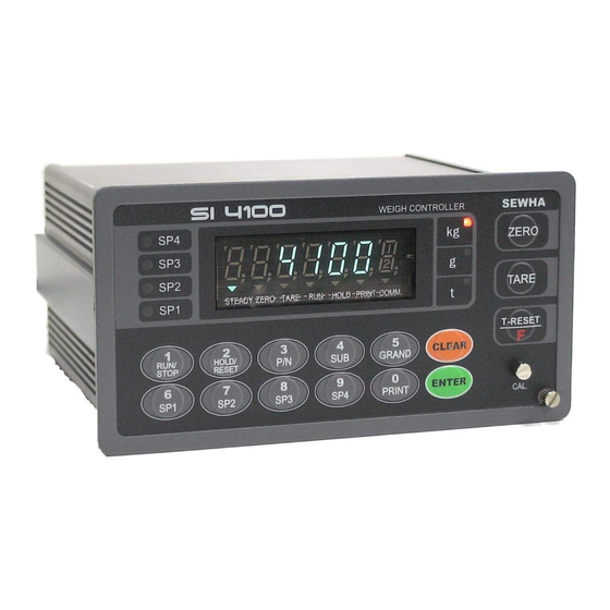
- Page 1 Digital Weighing Controller SI 4100 Instruction Manual...
- Page 2 Digital Weighing Indicator SI 4100 CONTENTS --------------- 1. Before Installation 3 page 2. Introduction --------------- 4 page 3. Specification ---------------- 5 page 4. Installation --------------- 11page 4-1. External Dimension & Cutting Size --------------- 11 page 4-2. Load Cell Installation --------------- 12 page 4-3.
- Page 3 1-3. Copy Rights 1).All Right and Authority for this Manual is belonged to Sewhacnm Co.,Ltd. 2).Any kinds of copy or distribution without Sewhacnm Co.,Ltd’s permission will be prohibited. 1-4. Inquiries If you have any kinds of inquiries for this model, please contact with your local agent or Head Office.
- Page 4 With 2ports serial port communication and precise weighing control system, you can upgrade your weighing process. This “SI 4100” Weighing Controller has various kinds of “Weighing Mode”, like Limit, Packer, and Check weighing Mode, so you can apply various kinds of weighing applications.
- Page 5 Digital Weighing Indicator SI 4100 3. SPECIFICATION 3-1. Analog Input & A/D Conversion Input Sensitivity 0.3㎶ / Digit DC 10V ( - 5V ~ + 5V ) Load Cell Excitation Max Input Signal Max3.2mV/V [Zero] ±16PPM/℃ Temperature Coefficient [Span] ±3.5PPM/℃...
- Page 6 Digital Weighing Indicator SI 4100 3-4. Option Card Option No.1 Printer Interface : Centronics Parallel Analog Output (0~10V or 0~5V) Option No.2 Option No.3 Analog Output (4~20mA) Serial Interface : RS-232C / 422 / 485 Option No.4 BCD INPUT (P/N change purpose) Option No.5...
- Page 7 No.(Press function No. and press “F” key) 3. Function key (Refer “Function keys”) To START or STOP weighing process. First input, SI 4100 Controller Starts weighing process, and Second input, SI 4100 Controller stops weighing process. ※ This function will be activated under F21- setting, only.
- Page 8 Digital Weighing Indicator SI 4100 Under Print installation, you can print out the “Sub-total data” of current P/N. Printed Data : Accumulated count and weight of current P/N. Under Print installation, you can print out the “Grand-total data” of current P/N.
- Page 9 Digital Weighing Indicator SI 4100 1. Modify the set value during setting process. 2. Calibration mode - Move back to previous step. 3. F-function setting mode - Change F-function No. F-function no.(number key) + Clear directly move to that F-function 4.
- Page 10 Digital Weighing Indicator SI 4100 3-6. Rear Panel ② ○ ○ ○ ○ ○ ○ ○ ○ POWER AC IN - Power switch : Power on/off switch. Warning - Fuse : AC250V / 0.5A , φ5.25 , 20mm. - AC IN : Available Input AC 110V / 220V.
- Page 11 Digital Weighing Indicator SI 4100 4. INSTALLATION 4-1. External Dimension & Cutting Size (External Dimension) (Unit :mm) (Cutting Size) (Unit : mm) 4-2. Installation Components Power Cable Communication Connector(D-SUB 9P) Load-cell Cable - 11 -...
- Page 12 Digital Weighing Indicator SI 4100 4-3. Load Cell Installation 4-3-1. Load Cell Connector Specification RED(EXC+) WHITE(EXC-) GREEN(SIG+) BLUE(SIG-) YELLOW(SHLD) 4-3-2. Load Cell Installation 1) You can connect Max 8pcs of same capacity Load cells at once. (350Ω) 2) You have to make horizontal balance on the ground.
- Page 13 SI 4100 4-2-3. Formula to plan the precise weighing system This “SI 4100” weighing controller’s Max input sensitivity is 0.2㎶ / Digit. And for precise weighing system, the following formula must be satisfied. Caution : “Input sensitivity” means Min. output voltage variation of weighing part to change 1digit.
- Page 14 Digital Weighing Indicator SI 4100 5. SET-UP 5-1. Calibration Calibration is the process of adjusting weight balance between “Real weight” on the load cell and “Displayed weight of Indicator”. When you replace LOAD CELL or Indicator, you have to do Calibration process once again 5-2.
- Page 15 Digital Weighing Indicator SI 4100 p 20. 0 00 6. Press key to save and move to next step. 7. Define the optimal Digit/Division value of weighing measurement. Whenever you press key, the Digit/Division value will be changed in order of “1 2 5 10 20 50” .
- Page 16 Digital Weighing Indicator SI 4100 l 2. 0 00 12. Input the weight of your “Test weight”. And press key. Ex) Load Cell CAPA : 20kg, division 0.001 Use test weight which is at least 10% of max CAPA(20kg) = minimum 2kg of test weight is needed.
- Page 17 Digital Weighing Indicator SI 4100 5-3. Simulation Calibration Mode (Calibrate without Test weight) Through this “Simulation Calibration Mode” you can do simple calibration process without Test weight. This calibration mode uses “Load cells’ max capacity” and “Rated output value(mV)”. Simulation calibration’s degree of accuracy is lower than test weight calibration.
- Page 18 Digital Weighing Indicator SI 4100 6. Define the optimal position or decimal point p 30. 0 0 Whenever you press key, the location of decimal point will be changed. p 30. 0 0 7. Press key to save Digit / Decimal point and move to next step.
- Page 19 Digital Weighing Indicator SI 4100 Cell0Ut 12. At this step input Max Output rate(mV) of load cell. o1. 9 8900 13. Input Load cell Output Rate(mV/V) (refer the load cell label) Ex) Load cell Related output : 1.989 mV/V ※ Caution : Due to some variation between “Stated output rate” and “Real Output rate” of load cell, there might be some weight difference after finishing calibration.
- Page 20 SI 4100 5-4. Set-up Set-up means set the F-function and make SI 4100 weighing controller will perform more accuracy. (Considering external / internal environmental condition) ※remarks : In case that “P-W” is displayed, you have to check the pass word.
- Page 21 Digital Weighing Indicator SI 4100 5-5. F-Function ■ General Function Setting (“●” Factory default set value) Weighing Data Save Method Selection (Apply on Accumulated weighing count/weight) Manual Save Mode (Save when “Print” key input) ● Automatic Save Mode(Save when Finish relay Output) Combined Save Mode (Save when “Print”...
- Page 22 Digital Weighing Indicator SI 4100 Zero key Operation Range selection Activated within 2% of Max Capacity Activated within 5% of Max Capacity ● Activated within 10% of Max Capacity Activated within 20% of Max Capacity Activated within 50% of Max Capacity Activated within 100% of Max Capacity Whenever Press “Zero”...
- Page 23 Digital Weighing Indicator SI 4100 Display Up-date rate selection (per sec) ● 238 times 102 times 64 times 47 times 34 times 31 times 26 times 23 times 20 times 18 times Sp1, Sp2, Sp3, Sp4 Set value apply selection ●...
- Page 24 Digital Weighing Indicator SI 4100 ■ Relay Output Mode Setting Weighing Mode selection Limit Mode 1. (Relay “ON”, when current weight reaches set value) ● Packer Mode Check weighing Mode 1. Check weighing Mode 2. Limit Mode 2. (Relay “OFF”, when current weight reaches set value) User’s Choice Relay Output Mode 1.
- Page 25 Digital Weighing Indicator SI 4100 ◆ Weighing Mode 1. Limit Mode 1. (F21-01 setting) - Relay “ON” when weight reaches to set value 1. Set value setting Sp1(Bulk), Sp2(Bulk + Drib), Sp3(Bulk + Drib + Fall), Sp4(FINAL) Setting conditions : (Sp4>Sp3>Sp2>Sp1) ※...
- Page 26 Digital Weighing Indicator SI 4100 ◆ Weighing Mode 2. Packer Mode (F21-02 setting) 1. Set value setting Sp1(Bulk), Sp2(Bulk + Drib), Sp3(Bulk + Drib + Fall), Sp4(FINAL) Setting conditions : (Sp4>Sp3>Sp2>Sp1) ※ If the setting conditions are not satisfied, “E” symbol displayed and you can process the weighing.
- Page 27 Digital Weighing Indicator SI 4100 ◆ Weighing Mode 3. Comparison Mode (F21-03 setting) - Checker Mode 1. Weight Near Zero TARE(IN) Near Zero ≤Steady weight<SP1 t3 t4 SP1≤Steady weight<SP2 t3 t4 SP2≤Steady weight<SP3 t3 t4 SP3≤Steady weight<SP4 t3 t4 SP4≤Steady weight...
- Page 28 Digital Weighing Indicator SI 4100 ◆ Weighing Mode 4. Packer Mode (F21-04 setting) - Checker mode 2. Weight Near Zero TARE(IN) Near Zero≤ Steady weight<SP1 SP1≤Steady weight<SP2 SP2≤Steady weight<SP3 SP3≤Steady weight<SP4 SP4≤Steady weight Near Zero 1. Set value setting Sp1(Acceptable Range), Sp2 (Acceptable Range), Sp3(Acceptable Range), Sp4(Acceptable Range) 2.
- Page 29 Digital Weighing Indicator SI 4100 ◆ Weighing Mode 5. Limit Mode 2. (F21-05 setting) - Relay “OFF” when weight reaches to set value 1. Set value setting Sp1(Bulk), Sp2(Bulk + Drib), Sp3(Bulk + Drib + Fall), Sp4(FINAL) Setting conditions : (Sp4>Sp3>Sp2>Sp1) ※...
- Page 30 Digital Weighing Indicator SI 4100 ◆ Weighing Mode 6. User’s Choice Mode 1. (F21-06 setting) - User Can arrange each relay output (SP1~4) sequence, by setting each SP value. (“B” Dry Contact) - Example. User’s Relay output Sequence : SP3SP1SP4SP2FinishNear Zero SP settings : SP3(100kg), SP1(200kg), SP4(300kg), SP2(400kg) 1.
- Page 31 Digital Weighing Indicator SI 4100 ◆ Weighing Mode 7. User’s Choice Mode 2. (F21-07 setting) - User Can arrange each relay output (SP1~4) sequence, by setting each SP value. (“A” Dry Contact) - Example. User’s Relay output Sequence : SP3SP1SP4SP2FinishNear Zero SP settings : SP3(100kg), SP1(200kg), SP4(300kg), SP2(400kg) 1.
- Page 32 Digital Weighing Indicator SI 4100 ◆ Weighing Mode 8 Accumulating Mode 1 (F21-08 Setting) 1. Set Value Setting SP1, SP2, SP3, SP4 > “Empty(Near Zero) Range. ※ SP1, SP2, SP3, SP4 = 0, The relay is not used. Sp1(No.1 Material Set value), Sp2(No.2 Material Set value), Sp3(No.3 Material Set value), Sp4(No.4 Material Set value) There is any condition to set the each set value.
- Page 33 Digital Weighing Indicator SI 4100 ◆ Weighing Mode 9. Packer mode User’s Choice 2 (F21-09 Setting) 1. SP1, SP2, SP3, SP4 can be any value. ※ SP1, SP2, SP3, SP4 = 0, The relay is not used. 2. Finish relay output delay time(t1) setting : F-Function 22 3.
- Page 34 Digital Weighing Indicator SI 4100 ◆ Weighing Mode 10 Accumulating Mode 2 (F21-10 Setting) 1. SP1, SP2, SP3, SP4 can be any value. ※ SP1, SP2, SP3, SP4 = 0, The relay is not used. 2. Finish relay output delay time(t1) setting : F-Function 22 3.
- Page 35 Digital Weighing Indicator SI 4100 “FINISH Relay” delay time(t1) setting (Under F21- 01, 02, 05 setting) After current weight is reached to FINAL, you can set some delay time of “FINISH relay ON time. Steady point ∫ FINISH Relay Com-Out4 “00”...
- Page 36 Digital Weighing Indicator SI 4100 “STEADY” Judging “ON” time(t4) setting (Only for F21-03, Check mode1.) You can set duration time for Error relay Steady point ∫ Com-Out5 “01” setting : ERROR relay will be “ON during 0.1sec. “20” setting : ERROR relay will be “ON” during 2.0sec.
- Page 37 Digital Weighing Indicator SI 4100 76,800bps 115,200bps DATA Transference Method selection ● Simplex Mode / Stream Mode Duplex Mode / Command Mode Print port selection (Under F32-01 setting, only) ● Same port as using for Command Mode. The other port.
- Page 38 Digital Weighing Indicator SI 4100 Print Format selection (If you install on Standard Serial Port) ● Continuous Print : Serial No. and Weight will be printed continuously. Single Print : Date, Time, S/N, ID No. Weighing Data will be print Print Format selection (If you install on Optional Serial Port) ●...
- Page 39 Digital Weighing Indicator SI 4100 Analogue Output Selection (Under 4~20mA Option Card Installed) ● 20mA Output, When Display weight is same as Max Capacity 20mA Output, When Display weight is same as SP1 set value 20mA Output, When Display weight is same as SP2 set Value...
- Page 40 Digital Weighing Indicator SI 4100 SPAN Calibration Value Check Span Calibration Value Check Under F-function mode, enter “ ”, “ ” key and press “ ”. X.X.X.X.X.X. After checking the value and press “ ” to exit ※ If you have difficulty to process Calibration again, the best way to matching the net weight and display weight is doing Calibration process once again.
- Page 41 Digital Weighing Indicator SI 4100 Serial Communication Speed selection 2,400bps 4,800bps ● 9,600bps 14,400bps 19,200bps 28,800bps 38,400bps 57,600bps 76,800bps 115,200bps DATA Transference Method selection ● Simplex Mode / Stream Mode Duplex Mode / Command Mode Print port selection (Under F62-01 setting, only) ●...
- Page 42 Digital Weighing Indicator SI 4100 6. INTERFACE 6-1. Serial Interface (RS-232C) RS-232C Serial Interface is sensitive/weak for electric Noise. So, please isolate with AC power cable and use shield cable to reduce the electric noise effect. 6-1-1. Communication with PC(Personal Computer) or Other devices...
- Page 43 Digital Weighing Indicator SI 4100 Start Bit Data Bit Parity Bit Stop Bit 6-1-4 Data Format(1) : ID Number will not be transferred. (Refer “F-function 37”) Including Decimal point Header 1. Header 2. Data Byte ( 7 or 8 byte )
- Page 44 Digital Weighing Indicator SI 4100 ② Header 2. : NT : Net-Weight GS : Net-Weight, under TARE. ③ Data Bit(Number) 2B(H) : “+” Plus 2D(H) : “-“ Minus 2D(H) : “ “ Space 2E(H) : “.” Decimal Point ④ Unit : kg, g, t 6-1-6 Data Format(3) : CAS “CI5101A”...
- Page 45 Digital Weighing Indicator SI 4100 6-1-7. Data Format : AD – 4321 Data Transference) – AD – 4321 18byte Format +,- / Including Decimal point 8byte Weight Header 1 Header 2 Data(8) Unit ① Header 1. : OL : Over Load, Under Load ST : Display “Steady”...
- Page 46 Digital Weighing Indicator SI 4100 6-2. Current Loop Interface “Current Loop” Interface is stronger for Electric Noise than “RS-232C” interface. So, it can be used for long distance communication.(About 100m long distance). ※ Current Loop Interface supports, up to 9,600 Communication Speed, only.
- Page 47 Digital Weighing Indicator SI 4100 6-3. Print Interface (Option 01 : Centronics Parallel Interface) This Print Interface Option is based on “Centronics Parallel Interface”, so this print interface can be connected other printers using this communication method. But, the print format is programmed based on our “SE7300”, and “SE7320” Industrial Printers, so you had better to use these printer for convenience.
- Page 48 Digital Weighing Indicator SI 4100 6-3-2 Print Format (English) Single Print Format Continuous Print format DATE : 2006-10-15 Date : 2006-10-15 TIME : 10:20:30 Time : 10:20:30 ID_N PART SERIAL WEIGHT ID_N PART SERIAL WEIGHT + 1.000 kg + 1.000 kg + 1.000 kg...
- Page 49 Digital Weighing Indicator SI 4100 6-4. Analog Output Interface (Option 02 : 0~10V Output) This Option card converts weight value to Analog Voltage output(0~10V) and transfers to external devices(Recorder, P.L.C), controlled by voltage output. 6-4-1. Specification ① Output Voltage : 0~10V DC output ②...
- Page 50 Digital Weighing Indicator SI 4100 6-5. Analog Output Interface (Option 03 : 4~20mA Output) This Option card converts weight value to Analog Electric Current output(4~20mA) and transfers to external devices(Recorder, P.L.C), controlled by electric current output. 6-5-1. Specification ① Output Current : 4~20mA (Output Range : 2~22mA) ②...
- Page 51 Digital Weighing Indicator SI 4100 6-6. Serial Interface (option 04 : RS-232C/422/485) RS-422/485 serial interface is more stable for electric noise effect compare with other communication method, using electric current difference. But, install isolated place from Power cable or other electric cables and wires, and please use shielded cable for better performance.
- Page 52 Digital Weighing Indicator SI 4100 6-7. BCD Input ( Option 05) – Input for Part No. selection. This “BCD interface” option card can be applied on PLC (Programmable Logic Controller), or Score Board applications. (NPN TYPE) Each Input circuit is isolated with “Photo-Coupler”, from external devices electrically.
- Page 53 Digital Weighing Indicator SI 4100 6-8. BCD Output Interface( Option 06) This “BCD interface” option card can be applied on PLC (Programmable Logic Controller), or Score Board applications. Each Input circuit is isolated with “Photo-Coupler”, from external devices electrically. - 53 -...
- Page 54 Under “Command Mode”, Indicator will recognize the receipt of Order based on 02h(Header) and 03h(END) signal, and transfers ACK(06)/ NAK(15). 6-9-1. Read Command (Standard Serial Port and Optional Port is same.) P.C ->> SI 4100 Command SI 4100 Response Current Weight Transfer STX ID NO.
- Page 55 STX ID NO. RWRS ETX situation +/- (1byte) current weight(7/8byte),input situation(4byte),relay (weight, relay output) output(6byte).ETX 6-9-2. Write Command P.C ->> SI 4100 Command SI 4100 Response STX ID NO. WZER ETX To make Current Weight as Zero ACK or NAK STX ID NO.
- Page 56 Digital Weighing Indicator SI 4100 7. Error & Treatment 7-1. Load Cell Installation Error Cause Treatment Remark 1. Input Resistance of 1.Load cell broken 1. Measure “EXC+” and “EXC-“ is 2. Load cell isolation input/output resistance about 400Ω ±30 resistance error of Load cell.
- Page 57 Digital Weighing Indicator SI 4100 7-3. Digital Weighing Indicator Error Display Cause Treatment 1. Under “TEST” mode 1, check analogue value. If you can not get any analogue value 1. Load cell Error or there is no change although adding load, “CELL-...
- Page 58 Digital Weighing Indicator SI 4100 7-4. Indicator Test mode Through this “Test Mode”, you can check basic conditions of Indicator. This Test consist with total 7 tests. 7-4-1. Enter “Test Mode” key for 4sec, then display will show “F-Test”. Press Under this display, press No.2 key and enter the “Test Mode”.
- Page 59 Digital Weighing Indicator SI 4100 WARRANTEE CETIFICATION This product is passed “Sewhacnm”s strict quality test. If there is defect of manufacturing or abnormal detection within warrantee period, please contact our Agent or Distributor with this Warrantee certificate. Then, we will repair or replace free of charge.
Need help?
Do you have a question about the SI 4100 and is the answer not in the manual?
Questions and answers