Table of Contents
Advertisement
Advertisement
Table of Contents

Summary of Contents for Murzan PI-50
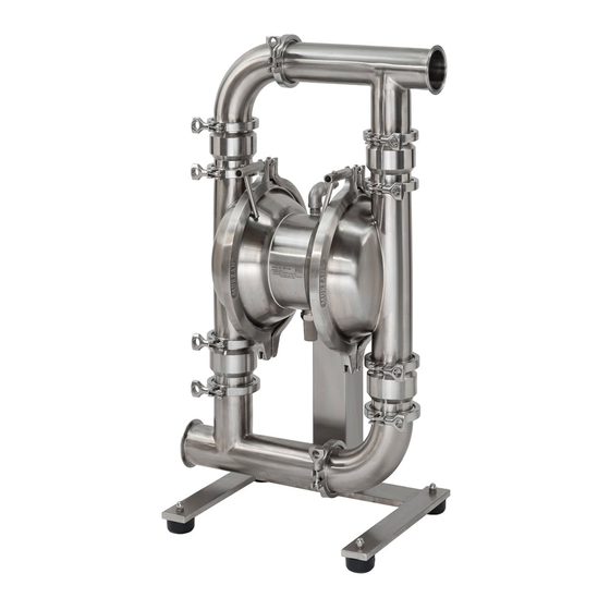
- Page 1 OPERATION & SERVICE MANUAL MURZAN PI-50 PUMP UNIT SERIAL NUMBER 123A IMPORTANT DOCUMENTATION, DO NOT DISCARD CE DECLARATION OF CONFORMITY AVAILABLE MURZAN INC. 2909 LANGFORD RD. 1-700 NORCROSS, GA 30071 UNITED STATES OF AMERICA TEL: (770) 448-0583 FAX: (770) 448-0967...
- Page 2 When calling to request parts or information about your Murzan pump, please have your serial number and pump key (both below) ready. Serial number: 123A Pump key: PI-50 - SL - V - HV MC - IB3 - 3Mx3M - FG/TF/FG - BDA - HT - S MURZAN SERIAL NUMBER...
-
Page 3: Table Of Contents
TABLE OF CONTENTS 1.0 Air Quality ..........................1 2.0 Basic Operation ........................2 3.0 Maintenance and Cleaning ...................... 3 3.1 Clean In Place ........................4 4.0 Pump Subassemblies ....................... 5 4.1 Center Subassembly ......................8 4.2 Chamber Subassembly ....................10 4.3 Check Valve Subassembly .................... -
Page 4: Air Quality
1.0 AIR QUALITY Your Murzan Pump is powered with compressed air at a maximum pressure of 100 PSIG. DO NOT EXCEED THIS LEVEL, as damage to the system or personal injury may occur. Murzan pumps use a non-lubricated air valve system to meet the stringent USDA and FDA standards required for pneumatically operated diaphragm pumps in the food and pharmaceutical industries. -
Page 5: Basic Operation
2.0 BASIC OPERATION Your Murzan Pump has wetted parts constructed of 304 or 316 stainless steel and FDA approved elastomers. When using the pumps in a permanent installation attached to rigid piping, the use of flexible couplings on both the suction and discharge ports of the pump is recommended to reduce vibration due to the reciprocating nature of the pump. -
Page 6: Maintenance And Cleaning
In general, cleaning requirements and guidelines are set by governmental agencies such as the USDA or FDA in the United States. Each user of Murzan Inc. equipment is responsible for ensuring that their cleaning process and procedures meet the applicable governmental and industry standards. -
Page 7: Clean In Place
If you are cleaning your Murzan pump along with your piping system at the same time, a bypass hose should be used to provide the additional flow required. It is recommended that the minimum flow rate for CIP of your Murzan pump be 5 ft/sec (1.5 m/s). Please refer to the CIP Diagram in section 10.0. -
Page 8: Pump Subassemblies
Note: the manifolds, check valves, and chambers on the following page may be different than those of your pump. However, the four main subassemblies remain the same for any Murzan pump. The tables and diagrams in sections 4.1-4.4 give detailed listings of the respective subassembly components, specific to your Murzan pump. -
Page 9: Center Subassembly
CENTER SUBASSEMBLY CHAMBER SUBASSEMBLY CHECK VALVE SUBASSEMBLY MANIFOLD SUBASSEMBLY DATE: DESCRIPTION: CREATED BY: 2909 LANGFORD RD. 1-700 DRAWING No. NORCROSS, GA. 30071 USA TEL: (770) 448-0583 FAX: (770) 448-0967... -
Page 10: Pump Assembly
PUMP ASSEMBLY DATE: DESCRIPTION: CREATED BY: 2909 LANGFORD RD. 1-700 DRAWING No. NORCROSS, GA. 30071 USA TEL: (770) 448-0583 FAX: (770) 448-0967... - Page 11 4.1 CENTER SUBASSEMBLY PARTS (Diagram 1 on next page) Part Description Label # Part # MC-V-HT Center Block 110011000 MC/LC Block Gasket Set 110010071 Assembly A 110021000 Assembly B 110031000 Assembly C 110041000 Air inlet filter 110010020 Muffler 110010010 Air Connector 1/2" 110010030 Nipple 1/2"...
- Page 12 NOTES: P R O P R I E T A R Y I N F O R M A T I O N REV DESCRIPTION DATE DATE: DESCRIPTION: CREATED BY: 2909 LANGFORD RD. 1-700 DRAWING No. NORCROSS, GA. 30071 USA TEL: (770) 448-0583 FAX: (770) 448-0967...
- Page 13 4.2 CHAMBER SUBASSEMBLY PARTS (Diagram 2 on next page) Part Description Label # Part # MC BDA FG Diaphragm 110091010 HV MC 3'' Product Chamber 110103300 Air Chamber MC 110081000 MC Shaft 110061000 MC BDA Piston Inner 110070110 MC BDA Piston Outer 110071100 Piston Inner Washer MC/LC 110070011...
- Page 14 NOTES: P R O P R I E T A R Y I N F O R M A T I O N REV DESCRIPTION DATE DATE: DESCRIPTION: CREATED BY: 2909 LANGFORD RD. 1-700 DRAWING No. NORCROSS, GA. 30071 USA TEL: (770) 448-0583 FAX: (770) 448-0967...
- Page 15 4.3 CHECK VALVE SUBASSEMBLY PARTS (Diagram 3 on next page) Part Description Label # Part # 2 1/4'' Ball HF 110153310 3" Ball/Mushroom Housing 110143300 3" Ball Stop 110156300 3" Clamp 110124300 3" FG Gasket 110095300...
- Page 16 NOTES: P R O P R I E T A R Y I N F O R M A T I O N REV DESCRIPTION DATE DATE: DESCRIPTION: CREATED BY: 2909 LANGFORD RD. 1-700 DRAWING No. NORCROSS, GA. 30071 USA TEL: (770) 448-0583 FAX: (770) 448-0967...
- Page 17 4.4 SUCTION/DISCHARGE MANIFOLD SUBASSEMBLY PARTS (Diagram 4 on next page) Part Description Label # Part # 3"x 3" 90 Elbow 110193300 3" Tee, MC M Manifold 110181330 3" Clamp 110124300 3" FG Gasket 110095300...
- Page 18 NOTES: P R O P R I E T A R Y I N F O R M A T I O N REV DESCRIPTION DATE DATE: DESCRIPTION: CREATED BY: 2909 LANGFORD RD. 1-700 DRAWING No. NORCROSS, GA. 30071 USA TEL: (770) 448-0583 FAX: (770) 448-0967...
-
Page 19: Pump Disassembly
5.0 PUMP DISASSEMBLY The following section detials the disassembly of your Murzan PI-50 pump. The diassembly process is divided in two parts, as mentioned in the earlier section on maintenance: disassembly of wet pump parts (for cleaning) followed by disassembly of dry pump parts (for maintenance). - Page 20 (3/3) from all check valves. 4. Loosen left product chamber clamp 5. Remove left product chamber clamp All wet parts of your Murzan pump (2/8) by turning clamp handle (2/9). and left product chamber (2/2). Repeat are now exposed for inspection and for right product chamber.
- Page 21 (Pump disassembly, continued.) To continue pump disassembly, you will need the following tools: . (2) 3/4'' Open end wrench . (1) 1'' Combination wrench . (1) Adjustable wrench . (1) Ratchet with extension . (1) 9/16'' Socket . (1) 7/16'' Socket 6.
-
Page 22: Assembly A
5.1 ASSEMBLY A The Assembly A is a wear part and will require replacement. We recommend replacement at least every 6 to 12 months depending on use of pump, for optimal pump performance. If your pump is shifting erratically or stalling, replace Assembly A immediately. The following instructions will guide you through the disassembly and reassembly of Assembly A. - Page 23 DATE: DESCRIPTION: CREATED BY: 2909 LANGFORD RD. 1-700 DRAWING No. NORCROSS, GA. 30071 USA TEL: (770) 448-0583 FAX: (770) 448-0967...
-
Page 24: Assembly B
5.2 ASSEMBLY B Assembly B should be replaced whenever Assembly A is replaced, or every 6 to 12 months for optimal pump performance. The following instructions will guide you through disassembly and reassembly of Assembly B, shown on the following page in Diagram B. To begin disassembly and reassembly of Assembly B, you will need the following tool: . - Page 25 NOTES: P R O P R I E T A R Y I N F O R M A T I O N REV DESCRIPTION DATE DATE: DESCRIPTION: CREATED BY: 2909 LANGFORD RD. 1-700 DRAWING No. NORCROSS, GA. 30071 USA TEL: (770) 448-0583 FAX: (770) 448-0967...
-
Page 26: Assembly C
5.3 ASSEMBLY C Assembly C does not normally require replacement. These instructions will guide you through disassembly and reassembly of Assembly C, shown on the following page in Diagram C. To begin disassembly and reassembly of Assembly C, you will need the following tool: . - Page 27 NOTES: P R O P R I E T A R Y I N F O R M A T I O N REV DESCRIPTION DATE DESCRIPTION: DATE: CREATED BY: 2909 LANGFORD RD. 1-700 DRAWING No. NORCROSS, GA. 30071 USA TEL: (770) 448-0583 FAX: (770) 448-0967...
-
Page 28: Pump Reassembly
6.0 PUMP REASSEMBLY Pump parts are referenced in the instructions below using the following notation: Diagram #/Item #. (For example, 4/2 refers to Diagram #4, Item #2.) For pump reassembly of wet parts, skip ahead to step 6. To begin pump reassembly of dry parts, you will need the following tools: . - Page 29 6. Place one of the product chambers (2/2) over the diaphragm, aligned with the air chamber. Install the product chamber clamp (2/8) and tighten the clamp handle (2/9) just enough to hold the product chamber in place. Use a torpedo level to ensure that the product chamber tube is perfectly perpendicular to the floor and then fully tighten the clamp handle.
- Page 30 7. Pull the opposite piston assembly through to the exposed air chamber. Again, fold the diaphragm inwards until it is flush with the air chamber. Place the product chamber over the diaphragm, install the product chamber clamp and tighten the clamp handle just enough to hold the product chamber in place. Again, check the level of the product chamber.
- Page 31 8. Insert balls (3/1) and stoppers (3/3) into the four housings (3/2) and install onto the product chambers using gaskets (3/5) and clamps (3/4). (Shown above, left) 9. Install the suction manifold using clamps (4/3) and gaskets (4/4). (Shown above, right) 10.
-
Page 32: Troubleshooting
7.0 TROUBLESHOOTING This section describes possible problems that could be encountered with your Murzan pump, as well as a list of possible causes and solutions. Contact Murzan for additional support. Pump will not cycle Check for adequate air supply (air pressure and volume) -
Page 33: Spare Parts
In many processing facilities requiring high product output, you may find it necessary to purchase spare parts to avoid unplanned down time. The following parts, specific to your Murzan pump, typically need replacing during years of continual service. Part #... -
Page 34: Terms Of Sale
Murzan, Inc. shall not be held liable for any losses or damages to the customer resulting from the improper operation, care or cleaning of GENERAL this equipment. -
Page 35: Additional Documents
10.0 ADDITIONAL DOCUMENTS Additional documents for your Murzan pump are attached. - Page 36 30.2 " (766 mm) 21.1 " (537 mm) NOTE: YOUR MURZAN PUMP MAY HAVE DIFFERENT CHECK VALVES AND/OR DIFFERENT SIZE MANIFOLDS. HOWEVER, DIMENSIONS SHOWN ABOVE REMAIN SPECIFIC TO YOUR PUMP. NOTES: P R O P R I E T A R Y I N F O R M A T I O N...
Need help?
Do you have a question about the PI-50 and is the answer not in the manual?
Questions and answers