
Summary of Contents for TSI Incorporated Certifier FA Plus
- Page 1 CERTIFIER FA PLUS ® TEST SYSTEM OPERATOR’S MANUAL P/N 1980560, REVISION J FEBRUARY 2016...
- Page 3 CERTIFIER FA PLUS ® TEST SYSTEM OPERATOR’S MANUAL P/N 1980560, REVISION J FEBRUARY 2016 U.S. & INTERNATIONAL TSI Instruments Ltd. (UK) Sales and Customer Service: Sales and Customer Service: (800) 874-2811 / +1(651) 490-2811 +44 (0) 1494 459200 Fax: Fax: +1(651) 490-3824 +44 (0) 1494 459700...
- Page 5 Copyright TSI Incorporated / 2010-2016 / All rights reserved. Address TSI Incorporated / 500 Cardigan Road / Shoreview, MN 55126 / USA Fax No. (651) 490-3824 Caution TSI flowmeters are not medical devices under FDA 510(k) and in no situation should be used for human measurements.
- Page 6 TSI's Customer Service department at (800) 874- 2811 / (1) 651 490-2811 (USA and International) or TSI Instruments in UK at: +44 (0) 1494 4 59200. Trademarks ® Certifier is a registered trademark of TSI Incorporated. ® Certifier FA Plus Test System...
-
Page 7: Table Of Contents
CONTENTS INTRODUCTION ....................... 1 Parts List ......................2 Glossary ......................6 1.2.1 Symbols on Display ................6 SETUP AND OPERATION ..................11 Keypad Functions ..................15 Power up ....................... 16 Display Navigation ..................17 2.3.1 Measurement Selection ..............20 2.3.2 Graph Measurement Selection ............21 2.3.3 Available Measurement Parameters .......... - Page 8 MAINTENANCE ...................... 41 Recharging the Batteries (as required) ............41 Replacing the Oxygen Sensor ..............41 Cleaning (as required) ................... 41 Factory Calibration (recommended yearly) ........... 42 Return Procedure ..................42 SPECIFICATIONS ....................43 Physical ......................43 Environmental ....................43 Power ......................
- Page 9 Figure 16. Example of Graph Screen ................17 Figure 17. Parameter Screen Features ................. 18 Figure 18. Graph Screen Features ................19 Figure 19. Measurement Selection Screen ..............20 Figure 20. Graph Measurement Selection Screen ............21 Figure 21. Parameter Definitions ................... 23 Figure 22.
- Page 10 (This page intentionally left blank) ® Certifier FA Plus Test System...
-
Page 11: Introduction
1 Introduction ® The Certifier Flow Analyzer (FA) Test System is a multi-functional pneumatic tester designed specifically for the medical industry. Specific measurements for ventilator testing are programmed and include flows, volumes, pressures, oxygen concentration, ® and breath timing. The Certifier FA Plus Test System is designed for hospital, home care, field service, and laboratory settings. -
Page 12: Parts List
The Certifier FA Plus is not a medical device under the Medical Device Directive or FDA 510(k) and in no situation should be used for human measurements. 1.1 Parts List Carefully unpack the test system components from the shipping container. -
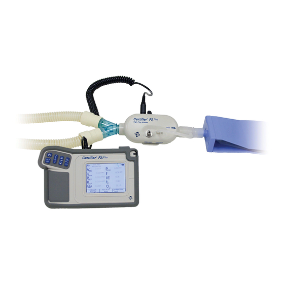
Page 13: Figure 1. Certifier ® Fa Test System High Flow Standard Kit (4080)
® Table 1. Certifier FA Test System Parts List Item Replacement Description Quantity Part Number High Flow Standard Kit (part number 4080) Interface Module 4088 High Flow Module 4081 Bacteria filter, 22-mm 22-mm male/female, for use 1602341 with High Flow Module Adapter, 22-mm 6-mm (for interfacing High Flow 1102091... -
Page 14: Figure 2. Certifier ® Fa Test System Low Flow Module Kit (4082)
® Figure 2. Certifier FA Test System Low Flow Module Kit (4082) Item Replacement Description Quantity Part Number Low Flow Module Kit (optional—part number 4082) 20 Low Flow Module 4082 21 Bacteria filter, for use with Low Flow Module 1602342 22 Mounting bracket (includes bracket, screws, and 1040044 Velcro strap) -
Page 15: Figure 4. Certifier Fa Test System Extra Battery And Charger Kit (1208061)
Item Replacement Description Quantity Part Number Oxygen sensor kit (optional—part number 4073) 25 Oxygen sensor 2917019 26 Threaded tee 1313118 27 Oxygen sensor cable 1303741 ® Figure 4. Certifier FA Test System Extra Battery and Charger Kit (1208061) Item Replacement Description Quantity Part Number... -
Page 16: Glossary
1.2 Glossary ® These labels, terms, and symbols appear on the Certifier FA Test System: ® FA Test System Operator’s Manual for Refer to manual: see Certifier important information. CE marking of European Conformity for the Low Voltage Directive (LVD) and the Directive for Electromagnetic Compatibility (EMCD). -
Page 17: Figure 5. Interface Module
Stylus Key Pad Touch Screen Display Figure 5. Interface Module 1: Introduction... -
Page 18: Figure 6. Back Of Interface Module
Module B Connector Module A Connector (not used) USB Connector SD Card Slot Wrist Strap Battery Cover Power Flip Out Stand Input Figure 6. Back of Interface Module ® Certifier FA Plus Test System... -
Page 19: Figure 7. High Flow Module (Arrow On Module Indicates Positive Flow Direction)
Low Pressure (150 cmH differential) Use “+” port for airway High Pressure Coiled Cable Connector (150 PSIG, 10 bar) pressure. Oxygen Sensor TTL Trigger Input Connector Figure 7. High Flow Module (arrow on module indicates positive flow direction) Coiled Cable Connector Figure 8. -
Page 20: Figure 9. Oxygen Sensor Kit
Figure 9. Oxygen Sensor Kit ® Certifier FA Plus Test System... -
Page 21: Setup And Operation
2 Setup and Operation ® Follow these steps to set up the Certifier FA Test System: Caution ® To avoid damage to the Certifier FA Test System components, always use bacteria filters upstream of the flow modules, and always cap flow module ports when not in use. -
Page 22: Figure 11. Installing A Flow Module Into The Circuit For Measuring Bi-Directional Flow (Flow Direction Arrow Should Be Towards Test Lung)
4. Install the flow module into the test circuit. Align the flow direction arrow on the flow module with the positive direction of flow through the circuit; for ventilator testing the arrow should point towards the test lung or away from the “To Patient” port on the ventilator. -
Page 23: Figure 12. Test Circuit For Bi-Directional Flow
Figure 12. Test Circuit for Bi-Directional Flow Note: If using a test lung with a built in restrictor or a separate restrictor, place the airway pressure fitting at least 15 cm of the 22 mm tubing between the restrictor and the flow module. If this is not done, the flow direction sensor may not work properly. -
Page 24: Figure 13. Removing Coupling
The low flow module is used for testing oxygen concentrators and other low flow devices. It is not designed for testing ventilators. The low flow module includes a push-to-fit tube fitting. To install, push tubes into coupling. To remove fittings, press or pry ring towards the coupling body with a small screwdriver while pulling coupling away from flow module. -
Page 25: Keypad Functions
2.1 Keypad Functions Figure 14. Interface Module Keypad Table 2. Keypad Functions Primary Function On/OFF key Zeroing Key—Press this key to zero the high and low pressure transducers. Print/Save Key—Press this key to print and/or save data. See Print/Save section (pg. 29) in this manual for more information. Press this key to switch between the Parameter Screen and Graph Screen. -
Page 26: Power Up
2.2 Power up If the device under test is running and creating flow or pressure, temporarily remove the flow module from the test circuit during power up. This allows the flow direction sensor on the high flow module to auto calibrate. ®... -
Page 27: Display Navigation
2.3 Display Navigation The main two screens are the Parameter Screen and the Graph Screen. Figure 15. Example of Parameter Screen Figure 16. Example of Graph Screen 2: Setup and Operation... -
Page 28: Figure 17. Parameter Screen Features
By touching on the active areas of the Parameter Screen, you can change the configuration of the display by choosing which parameters to monitor, units of measure, gas calibration, gas conditions, averaging, and triggering. You can also save the display configuration to a file or load a previously saved configuration. Stops/Starts data acquisition Figure 17. -
Page 29: Figure 18. Graph Screen Features
By touching on the active areas of the Graph Screen, you can change the configuration of the display by choosing which parameters to plot on the Graph, units of measure, gas calibration, gas conditions, averaging, triggering, x and y axis scale. -
Page 30: Measurement Selection
2.3.1 Measurement Selection Figure 19. Measurement Selection Screen To add a parameter to the Parameter Screen, touch the parameter and then touch the right direction arrow. The available parameters change depending on what module is attached. To remove a parameter from the Parameter Screen, touch the parameter and then touch the left direction arrow. -
Page 31: Graph Measurement Selection
2.3.2 Graph Measurement Selection Figure 20. Graph Measurement Selection Screen To add a parameter to Graph, touch the parameter on the left and then touch the top right direction arrow. Only two parameters can be graphed at one time. The available parameters change depending on what module is attached. -
Page 32: Available Measurement Parameters
2.3.3 Available Measurement Parameters Table 3. Parameters (parameter list changes depending on module attached) Flow Rate. “Q” is used on the High pressure transducer Graph Screen. (4081 only) Peak Flow Rate—Peak Inhaled Absolute pressure in flow tube. Flow Rate. “Qpeak” is used on If flow tube open to the Graph Screen. -
Page 33: Figure 21. Parameter Definitions
Figure 21. Parameter Definitions 2: Setup and Operation... -
Page 34: Gas Conditions Selection Box
2.3.4 Gas Conditions Selection Box Figure 22. Gas Conditions Selection Box Standard Temperature and Pressure. The gas flow rate and volumes are displayed in terms of what the gas flow rate and volume would be if the gas was 21°C and 1 atmosphere (101.3 kPa) of pressure. Actual Temperature and Pressure. -
Page 35: Averaging Setup Menu
2.3.5 Averaging Setup Menu Figure 23. Averaging Setup Menu Number of Breaths All breath parameters are averaged over the selected Averaged number of breaths. Second Average for All displayed transducer measurements are averaged over Real-Time Values the selected number of seconds. Transducer measurements include: flow, low pressure, high pressure, absolute pressure, oxygen concentration, and temperature. -
Page 36: Breath Trigger Types
2.3.6 Breath Trigger Types This screen defines how the start of the inspiratory breath cycle and the expiratory breath cycle are detected. Under most circumstances, it is recommended that the auto- trigger be used. Figure 24. Trigger Options Menu Flow Rate Start and end of the breath is determined by the specified flow rate. -
Page 37: Flow Triggering
1) switch the Certifier FA Plus Test System to the graphing screen and observe the flow or pressure readings at the start and the end of inspiration and 2) observe the flow and pressure wave form from the ventilator being tested. -
Page 38: Saving/Loading Configurations
2.3.8 Saving/Loading Configurations Configuration is saved under current name and location Figure 25. Configuration Save Screen Configuration of the values displayed, gas, conditions, triggering, and graph setup can be saved and recalled. This allows the user to save configurations for different equipment. -
Page 39: Print/Save Button
2.3.9 Print/Save Button Figure 26. Print/Save Options Screen If the Print/Save button is pressed while viewing the Parameter Screen, the "Print/Save Options" screen will appear. By selecting the various options on this screen you will be able to: Print the current data record without saving to a file. ... -
Page 40: Waveform Logging
Figure 27. Add Comments Screen If the Print/Save button is pressed while viewing the Graph Screen, you will be able to Save the currently displayed Graph data to a file to either the built-in Internal Memory or to an SD Flash card inserted into the SD Card slot. You cannot print the Graph or the Graph data and you cannot print or save a screen shot of the graph. -
Page 41: Continuous Logging
To initiate Waveform logging: Press the Print/Save button on the Certifier test system keypad. Select Waveform from the Logging Features section. You may choose to Add Comments if you would like to annotate the data. Click OK, add comments (if selected) and name the file. ... -
Page 42: Setup Key
2.3.10 Setup Key Figure 28. Setup Menu Oxygen Sensor Calibration See required pre-test section of this manual. Set Time/Date Sets the current time and date. Touch Screen Calibration Calibrates the touch screen of the interface module. Follow the instructions on the display. -
Page 43: Advanced Features
Select Mass Storage Target When the Certifier test system is connected to a host computer via USB interface, it appears to the host as a "mass storage" device, similar to a "memory stick" or “thumb drive”. This function allows you to select whether the host can access the Certifier's Internal Memory or an SD Flash memory card. -
Page 44: Format Settings
Notes about exporting configuration files: All data is saved to a single file called CertifierConfigurations.dat. If this file already exists on the SD card, it will be overwritten each time the Export command is executed. It is not possible to generate a user-selectable filename for the exported configurations. -
Page 45: Required Pre-Test Calibrations
Caution ® To ensure accurate measurements, wait one minute for the Certifier FA Test System to warm up. If environmental conditions have changed significantly, more time may be necessary. ® To avoid damage to the Certifier FA Test System components, always use bacteria filters upstream of the flow modules, and always cap flow module ports when not in use. -
Page 46: Oxygen Sensor Calibration
2.4.2.3 Oxygen Sensor Calibration Follow these steps daily and following an altitude change or sensor replacement to calibrate the oxygen sensor: ® 1. Power up the Certifier FA Test System with the High Flow Module and oxygen sensor attached, allow one minute to warm up. key and select the “Oxygen Calibration”... -
Page 47: Troubleshooting
3 Troubleshooting Table 4 lists the symptoms, possible causes, and recommended corrective actions for ® problems you may encounter with the Certifier FA Test System. If the symptom is not listed, or if none of the recommended corrective actions solve the problem, please visit our website at http://service.tsi.com or contact TSI Customer Support at (800) 874-2811... - Page 48 Symptom Possible Cause Corrective Action Volume, minute Less than two Wait for at least two consecutive volume, peak flow, consecutive full breaths full breaths to be supplied to the peak pressure, PEEP, have been supplied to flow module. respiratory rate, or I:E flow module, or flow is not ratio measurement are supplied as a breathing...
- Page 49 Symptom Possible Cause Corrective Action Oxygen sensor 21% oxygen and/or 100% Verify that calibration gases are calibration fails. oxygen not supplied for 21% oxygen and 100% oxygen calibration. and repeat calibration. Oxygen sensor is Replace oxygen sensor. expired. Use constant flow rates to Non-steady flow or tidal supply calibration gas.
- Page 50 (This page intentionally left blank) ® Certifier FA Plus Test System...
-
Page 51: Maintenance
The fastest charging method is to charge the battery in the instrument with the instrument turned off. The Certifier FA Plus uses SBL-160, Lithium Ion Batteries, which are available from many battery supply houses or TSI. -
Page 52: Factory Calibration (Recommended Yearly)
2. Package the flow modules carefully to avoid damage during shipping. NOTE: It is not necessary to return the Interface Module for factory calibration. U.S. & International United Kingdom TSI Incorporated TSI Instruments Ltd. 500 Cardigan Road Tel: (44) 1494 459200... -
Page 53: Specifications
5 Specifications NOTE: Specifications are subject to change without notice. 5.1 Physical Dimensions Interface module: 17.3 cm 10.5 cm 4.5 cm (6.8 in. 4.1 in. 1.8 in.) High Flow Module: 15 cm 6.7 cm 6.1 cm (5.9 in. -
Page 54: Data Transfer And Storage
5.4 Data Transfer and Storage 1 MB (500 typical records) Internal Memory External Memory SD Flash Card. Supports up to 1 GB cards. 5.5 Test Measurements See notes at end of section. See Table 3 for symbol definitions.) Measurement High Flow Module Low Flow Module Flows Range... - Page 55 Measurement High Flow Module Low Flow Module Volumes Range 0.01 to 10 L STP Not applicable Air and oxygen: 3% of reading Accuracy Not applicable plus 0.030 L Air/oxygen mixtures: 4% of reading plus 0.040 L STP Minute Volume Range 0.01 to 100 L STP 0 to 10 L STP 3% of reading...
- Page 56 Measurement High Flow Module Low Flow Module High Pressure Range -10 to 150.0PSIG (-0.7 to 10 Not applicable bar) 1% of reading or 0.1 PSI Accuracy Not applicable (7 mbar), whichever is greater. Absolute Pressure Range 375 to 1200 mmHg (500 to 375 to 1500 mmHg (500 to 1600 mbar) 2000 mbar)
-
Page 57: Calibration Recommendations
Measurement High Flow Module Low Flow Module NOTES 1. Standard conditions are defined as 21.1C (70F) and 101.3 kPa (14.7 psia). 2. Flow and volume accuracy is applicable at these standard conditions (see note 1). 3. For the High Flow Module the temperature of the gas and the ambient air must be within 10C (18F) of each other and the gas must be less than 30% relative humidity at 21.1C (70F). - Page 58 (This page intentionally left blank) ® Certifier FA Plus Test System...
-
Page 59: Appendix A Data File Formats
Appendix A Data File Formats Parameter Screen Single Sample and Continuous Logging Data Format Raw Text Example: Filename:,\NV1FLASH\EXAMPLE.csv Comments:,Custom comments here Configuration:,*Current Configuration Module A Model:,4081 Module A SN:,40810705010 Trigger Type:,Flow Rate Start Trigger:,Auto End Trigger:,Auto Module A Conditions:,STP Module A Gas:,AIR Data Section:,,Module A,Module A,Module A ,,Flow Rate,Low Pressure,PEEP Pressure Date,Time,L/Min,cmH2O,cmH2O... - Page 60 As Formatted By spreadsheet application: Filename: \NV1FLASH\EXAMPLE.csv Comments: Custom comments here Configuration: *Current Configuration Module A 4081 Model: Module A SN: 40810705010 Trigger Type: Flow Rate Start Trigger: Auto End Trigger: Auto Module A Conditions: Module A Gas: Data Section: Module A Module A Module A...
- Page 61 Raw Text Example (waveform logging): Appendix A Data File Formats...
- Page 62 Graph Screen Data Format The Graph Display data is formatted as 2 (1 parameter on Graph) or 3 (2 parameters on Graph) columns of text. The first column is the X axis (relative time), the second and third columns will contain the Graph data. Q L/Min P cmH2O Total graph time: 10 seconds.
- Page 63 TSI Incorporated – Visit our website www.tsi.com for more information. Tel: +1 800 874 2811 India Tel: +91 80 67877200 Tel: +44 149 4 459200 China Tel: +86 10 8219 7688 France Tel: +33 1 41 19 21 99 Singapore Tel: +65 6595 6388...
Need help?
Do you have a question about the Certifier FA Plus and is the answer not in the manual?
Questions and answers