Table of Contents
Advertisement
Advertisement
Table of Contents

Subscribe to Our Youtube Channel
Summary of Contents for Biolight V6
- Page 1 V6 Vital Signs Monitor User’s Manual...
-
Page 2: Product Information
Document No.: J/V6CE-A-010 Revision number: V3.1 Release time: 2013 Copyright © 2013 Guangdong Biolight Meditech Co., Ltd. All rights reserved. CE mark EC Representative Name: Shanghai International Trading Corp. GmbH (Hamburg) -
Page 3: About This Manual
Vital Signs Monitor User’s Manual Manufacturer holds the copyright of this manual, and we are also entitled to deal with this manual as confidential files. This manual is only used for operation, maintenance and service of product, someone else can not publish the manual. This manual contains exclusive information protected by copyright laws and we reserve its copyright. - Page 4 Vital Signs Monitor User’s Manual Bold Italic text is used in this manual to quote the referenced chapter or sections. 【】is used to enclose screen texts. → is used to indicate operational procedures.
-
Page 5: Table Of Contents
Vital Signs Monitor User’s Manual Contents Chapter 1 General Introduction..................1 1.1 Intended Use......................1 1.2 Main Unit........................1 1.3 Work mode....................... 5 Chapter 2 Safety.........................1 2.1 Safety Information....................1 2.2 Safe Operation Conditions..................4 2.3 Equipment Symbols....................4 Chapter 3 Operations......................1 3.1 Unpacking and Checking..................1 3.2 Getting Started......................2 3.3 Shutting off the Monitor..................3 3.4 Operation Modes......................3... - Page 6 Vital Signs Monitor User’s Manual 5.3 Alarm Indicators.......................2 5.4 Setting Alarm Volume.....................4 5.5 Parameter Alarm...................... 5 5.6 Pausing Alarms......................5 5.7 Silence........................6 Chapter 6 SpO ........................1 6.1 Introduction......................1 6.2 Safety Information....................1 6.3 Monitoring Procedure....................2 6.4 SpO Display......................2 6.5 Setting SpO ......................
- Page 7 Vital Signs Monitor User’s Manual Chapter 9 Temp......................... 1 9.1 Introduction......................1 9.2 Safety Information....................2 9.3 Monitoring Procedure....................2 9.4 Temp Display......................3 9.5 Setting Temp......................4 9.6 Temp Alarm......................4 9.7 Calibrating........................ 5 Chapter 10 Reviewing....................... 1 10.1 Entering the Reviewing Menu................1 10.2 Reviewing Details....................1 Chapter 11 Recording.......................
- Page 8 Vital Signs Monitor User’s Manual 14.1 SpO ........................1 14.2 NIBP........................2 14.3 CO (LoFlo)......................3 14.4 Temp........................3 14.5 Barcode scanner..................... 3 Appendix A Product Specifications................1 A.1 Safety Specifications....................1 A.2 Physical Specifications................... 2 A.3 Hardware Specifications..................2 A.4 Measurement Specifications.................. 5 Appendix B Factory Defaults..................
-
Page 9: Chapter 1 General Introduction
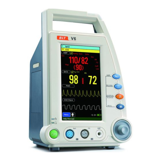
Vital Signs Monitor User’s Manual Chapter 1 General Introduction 1.1 Intended Use The monitor is intended to be used for monitoring, displaying, reviewing, storing and alarming of multiple physiological parameters of patients, including Pulse Oxygen Saturation (SpO ), Pulse Rate (PR), Non-invasive Blood Pressure (NIBP), Carbon dioxide (CO2) and Temperature (Temp). - Page 10 Vital Signs Monitor User’s Manual 1. Physiological alarm indicating lamp When a physiological alarm occurs, this lamp will light up as defined below: High level alarm: the lamp quickly flashes red. Medium level alarm: the lamp slowly flashes yellow. ...
-
Page 11: Side View
Vital Signs Monitor User’s Manual Power button Press this button to turn on the monitor after AC power is connected or the battery is installed. Press and hold it for 2 seconds to turn the monitor off. Power indicating lamp It is a LED that lights green and orange, the status of the LED is specified as follows: ... - Page 12 Vital Signs Monitor User’s Manual 1.2.3 Rear View Fig.1-3 1. Temp connector 2. Grounding terminal 3. AC power input connector onnect to USB device, such as keyboard and mouse. 4. Serial port 5. Wired network connector Standard RJ45 socket, it is used for connection with the central monitoring system provided by manufacturer.
-
Page 13: Work Mode
Vital Signs Monitor User’s Manual 1.2.4 Bottom View Battery compartment Fig.1-4 1.3 Work mode The monitor has two working modes: Clinic Mode and Monitor Mode. 1.3.1 Clinic Mode Clinic Mode refers to that the monitor is used for monitoring of a number of patients one by one by outpatient doctor. - Page 14 Vital Signs Monitor User’s Manual 1. Monitor of a single patient for a long time, e.g. hospitalized patient; 2. Ward without on-duty medical personnel; 3. Remote monitoring (connect to central unit through network). 1.3.3 Difference Between two Modes Monitor Clinic Function Mode Silence...
-
Page 15: Chapter 2 Safety
Vital Signs Monitor User’s Manual Chapter 2 Safety 2.1 Safety Information Warning Indicates a potential hazard or unsafe practice that, if not avoided, will result in death or serious injury. Caution Indicates a potential hazard or unsafe practice that, if not avoided, could result in minor personal injury or product/property damage. - Page 16 Vital Signs Monitor User’s Manual use battery to provide power to the monitor. To avoid explosion hazard, do not use the monitor in the presence of flammable anesthetics, vapors or liquids. Do not open the monitor housings; electric shock hazard may exist. All servicing and future upgrades must be carried out by the personnel trained and authorized by manufacturer only.
- Page 17 Vital Signs Monitor User’s Manual be disposed of in compliance with the guidelines regulating the disposal of such products. If you have any questions concerning disposal of the monitor, please contact us. Magnetic and electrical fields are capable of interfering with the proper performance of the monitor.
-
Page 18: Safe Operation Conditions
Vital Signs Monitor User’s Manual have all of them. The service life of this monitor is 5 years. At the end of its service life, the monitor, as well as its accessories, must be disposed of in compliance with the guidelines regulating the disposal of such products. - Page 19 Vital Signs Monitor User’s Manual Symbol Symbol Note Dangerous voltage Equipotential grounding 100V-240V~ Alternating current input range: 100V-240V USB socket Network connector Nurse call connector Manufacture date Manufacturer Serial number Degree of protection against ingress of liquid IPX1 Symbol marked on a tag attached to the supply cord of the monitor to Hospital Only warn that the supply cord should be connected to the sockets which are Hospital Only to achieve grounding reliability.
-
Page 20: Chapter 3 Operations
Vital Signs Monitor User’s Manual Chapter 3 Operations 3.1 Unpacking and Checking 1. Unpacking Before unpacking, examine the packing case carefully for signs of damage. If any damage is detected, contact the carrier. If the packing case is intact, open the package. 2. -
Page 21: Getting Started
Vital Signs Monitor User’s Manual 3.2 Getting Started 3.2.1 Inspecting the Monitor 1. Before you start to make measurements, carry out the following checks on the monitor including all connected modules. ——Check for any mechanical damage; ——Check for any incorrect connection of all the external cables and accessories. 2. -
Page 22: Shutting Off The Monitor
Vital Signs Monitor User’s Manual 3.2.3 Starting Monitoring 1. Decide which parameter should be monitored or measured. 2. Install required modules or sensors. 3. Check whether the installation of modules or sensors is correct. 4. Check whether all kinds of settings are correct. 5. -
Page 23: General Setup
Vital Signs Monitor User’s Manual under Monitor Mode is different from that under Clinic Mode. The following figure is main menu under Monitor Mode. Style of other menus is the same as that of the main menu, parts of which are as follows. -
Page 24: Default Setups
Vital Signs Monitor User’s Manual 3.6.4 Adjusting the Volume Alarm Volume Under the Monitor Mode: 1. Select【Menu】→【Sound Setup】. 2. Select【Alarm Volume】→choose a desired value. Beep Volume 1. Select【Menu】→【Sound Setup】. 2. Select【Beep Volume】→choose a desired value. 3.7 Default Setups Caution ... - Page 25 Vital Signs Monitor User’s Manual ——An alarm condition destined occurs. ——The monitor is not in the state of alarm paused or system silence. Warning The nurse call function should not be used as the primary patient alarm inform source. It is necessary for combining the auditory and visual alarm signal and the patient clinical feature and symptom as the primary information to medical and nursing staff about the physiological condition of the patient.
-
Page 26: Id Name
Vital Signs Monitor User’s Manual 3.9 ID Name You need to set ID name under the Clinic Mode. 1. 【Menu】→【System Setup】→【ID Name】 to enter ID Name menu. 2. Define the ID Name rule according to your usage. 3.10 Patient ID You can use a barcode scanner to input the Patient ID, please go through the following steps before input the patient ID: 1. -
Page 27: Chapter 4 User Interface
Vital Signs Monitor User’s Manual Chapter 4 User Interface Display Style Display style of user interface can be set according to your need. Including: ——Screen brightness. ——Display color of wave and parameter. ——Sweep mode of wave. 4.1.1 Adjusting the Screen Brightness 1. -
Page 28: Screen Layout
Vital Signs Monitor User’s Manual 4.2 Screen Layout The monitor has configured with a color TFT LCD to display parameters and waves of patient’s SpO , NIBP and CO . The following figures are screens of the monitor. 4.2.1 Standard Screen Parameters displayed under the screen are SpO , CO , SpO... - Page 29 Vital Signs Monitor User’s Manual 5. TEMP Parameter Area It is to display temperature parameter. Select “TEMP” to enter【TEMP Setup】 menu. 6. SpO Wave Area It is to display SpO wave. Select ” SpO Wave” to enter【SpO Wave Setup】 menu. 7.
- Page 30 Vital Signs Monitor User’s Manual 4.2.2 NIBP Review Under the screen, you can view the measurement of NIBP. 4.2.3 Trend Screen Chapter 4-4...
- Page 31 Vital Signs Monitor User’s Manual The screen is called “Trend Screen” under Monitor Mode while called “Clinic Review” under Clinic Mode. Under the screen you can view the measurement of each parameter. Storage Setup 1. Select【Menu】→【Storage Setup】to enter【Storage Setup】menu. Set【Trend StorInter】to a desired value between【1 Min】,【1 Min】and 【10 Min】.
- Page 32 Vital Signs Monitor User’s Manual 4.2.5 Trend Graph 5. Parameter displaying area 6. The selected parameter 7. Setting interval 4. Scale 3. Time scale 8. Cursor 2. Page down 2. Page up 1. Selecting parameter 9. Setting step You can enter TrendGraph screen through the screen changing button as shown in chapter 1 section 1.2 main unit.
-
Page 33: Patient Information
Vital Signs Monitor User’s Manual 4. Scale It is to scale the value of parameters. 5. Parameter displaying area It is to display values of all the monitored parameters at the time where the cursor indicates now. 6. The selected parameter It is to display the name of the selected parameter and its value at the time where the cursor is. -
Page 34: Demo
Vital Signs Monitor User’s Manual 4.3.2 Admitting a new patient When the patient to be monitored is a new one, please select 【New Patient】to enter【New Patient】menu. Input new patient’s ID, Name, Type, Gender and Age. At last,select【OK】to keep the setting of new patient. 4.3.3 Patient ID ... -
Page 35: Machine Maintenance
Vital Signs Monitor User’s Manual 3. Input the desired password and then select【OK】to enter the demo mode. 4.4.2 Turn off Demo 1. Select【Menu】→【System Setup】to enter the system setup menu. 2. Set【Demo】to【Off】. 4.5 Machine Maintenance Select 【Menu】→【System Setup】 →【Machine Mainte】 →input the required passwords to enter 【Machine Mainte】... -
Page 36: Chapter 5 Alarm
Vital Signs Monitor User’s Manual Chapter 5 Alarm Alarm refers to a prompt that is given by the monitor for medical personnel through visual, audible and other means when a vital sign appears abnormal or technical problem occurs. Note The monitor generates all the audible and visual alarms through speaker, alarm lamp and screen. -
Page 37: Alarm Level
Vital Signs Monitor User’s Manual 5.2 Alarm Level According to severity of alarm, the monitor’s physiological alarms are classified into three categories: high level alarms, medium level alarms and low level alarms. High level alarms: Indicate that the patient is in a life threatening situation and an emergency treatment is necessary. - Page 38 Vital Signs Monitor User’s Manual 5.3.1 Alarm Tone The different level alarms are indicated by the system in following different audio ways: Alarm level Audible prompt “DO-DO-DO------DO-DO, DO-DO-DO------DO-DO” High Medium “DO-DO-DO” “DO-” 5.3.2 Alarm Lamp When a physiological alarm occurs, the alarm levels are indicated in the following different visual ways: Alarm level Visual prompt...
-
Page 39: Setting Alarm Volume
Vital Signs Monitor User’s Manual 5.3.3 Alarm Message Physiological alarm Physiological alarm messages are displayed in the physiological alarm area. The system uses different symbols and background colors for the alarm messages to match the alarm level as follows: Alarm level symbol background color... -
Page 40: Parameter Alarm
Vital Signs Monitor User’s Manual 2. Select Alarm Volume desired value. 】→choose a 【 5.5 Parameter Alarm You need to set【Alarm Setup】only under Monitor Mode. 5.5.1 Turn on/off the Alarm Take SpO2 for example: 1. Select【Menu】→【Alarm Setup】. 2. Set【Class】to any option but【Off】to turn on the alarm, while set 【Class】 to【Off】to turn off the alarm. -
Page 41: Silence
Vital Signs Monitor User’s Manual Set the silence time only under Monitor Mode. 1. Select 【 Menu】 → 【System Setup】 → 【Machine Mainte】 →enter the required password. 2. Set【Alarm suspend Time】to【1Min】, 【2Min】or【3Min】. 5.7 Silence Press and hold the button on the front panel of monitor for 1 second to set the system silent. -
Page 42: Chapter 6 Spo
Vital Signs Monitor User’s Manual Chapter 6 SpO 6.1 Introduction The measurement of oxygen saturation of arterial blood (also known as pulse oxygen saturation, usually shortened as SpO ) adopts the principles of light spectra and volume tracing. The LED emits lights with two specific wavelengths, which are selectively absorbed by oxygenated hemoglobin and deoxyhemoglobin. -
Page 43: Spo Display
Vital Signs Monitor User’s Manual Before use, the operator must ensure the compatibilityies of the monitor, sensor and extension cables; otherwise, this may lead to the burning of patients; do not use damaged sensor or extension cable. Do not soak the sensor into water or make it wet, otherwise it may be damaged. - Page 44 Vital Signs Monitor User’s Manual “%” indicates SpO unit while “*” indicates signal intensity. Details are as the following table. value Pleth bar Pulse Rate (obtained from SpO Indicator of signal intensity Description “*” The signal strength is low. “**” The signal strength is good.
-
Page 45: Setting Spo
Vital Signs Monitor User’s Manual a) Perfusion index (PI): PI is a value that indicates arterial pulse signal strength as the percentage of pulsatile signal to non-pulsatile signal. The perfusion index allows clinicians to place sensors on optimal sites. b) Methemoglobin Saturation (SpMet): SpMet is a value that represents the percentage of methemoglobin saturation within the blood. - Page 46 Vital Signs Monitor User’s Manual 1. Select “Pleth” to enter【Pleth Setup】menu. 2. Set【Scan Speed】to 【6.25mm/s】,【12.5mm/s】,【25 mm/s】or【50 mm/s】 6.5.4 Setting Average Time The SpO reading shown on the monitor is the average of data collected within a specific time. The shorter the averaging time is, the quicker the monitor responds to the change in the patient’s oxygen saturation level.
- Page 47 Vital Signs Monitor User’s Manual is most difficult. The mode is recommended during procedures and when clinician and patient contact is continuous. 【Normal 】: This mode provides the best combination of sensitivity and probe-off detection performance. The mode is recommended for the majority of patients. 【APOD】: This mode is the least sensitive in picking up a reading on patients with low perfusion but has the best detection for probe-off conditions.
-
Page 48: Masimo Information
Vital Signs Monitor User’s Manual Setting SpHb Average Time You can select the averaging mode for SpHb value, select【SpHb Average Time】 in the SpO2 parameter setting menu, and you can select 【Short 】,【Medium】or 【Long】. Setting SpHb Precision You can select the SpHb precision to be displayed on the screen, select 【 SpHb Precision】in the SpO2 parameter setting menu, and select a proper time as required. -
Page 49: Chapter 7 Nibp
Vital Signs Monitor User’s Manual Chapter 7 NIBP 7.1 Introduction The monitor uses the oscillometric method for measuring NIBP. It is applicable for adult, pediatric and neonatal patients. The method of oscillometric indirectly estimates the systolic and diastolic pressures within the blood vessels by measuring the change of the pressure within blood pressure cuff along with the volume of the arteries and calculates the average pressure. -
Page 50: Measurement Limitations
Vital Signs Monitor User’s Manual 7.3 Measurement Limitations NIBP measurements are impossible with heart rate extremes of less than 40 bpm or greater than 240 bpm, or if the patient is on a heart-lung machine. The measurement may be inaccurate or impossible: ——with excessive and continuous patient movement such as shivering or convulsions;... - Page 51 Vital Signs Monitor User’s Manual Note The accuracy of measurement of BP depends on the suitability of the cuff. 3. Confirm the cuff has been entirely deflated. 4. Plug the air pipe plug of cuff into the connector (NIBP) of monitor until the plug and socket contact well.
-
Page 52: Nibp Display
Vital Signs Monitor User’s Manual 7.5.2 Starting/Stopping Measuring Press the button on the front panel of monitor to start NIBP measuring while press the button again to stop NIBP measuring. 7.5.3 Auto Measurement 1. Select ”NIBP” to enter【NIBP Setup】menu. 2. Set【Interval】to any option but【Manual】. 3. -
Page 53: Setting Nibp
Vital Signs Monitor User’s Manual 1. Pressure unit 2. Systolic blood pressure 3. Mean arterial blood pressure 4. Pulse Rate (obtained from NIBP) 5. Diastolic blood pressure 7.7 Setting NIBP Select ”NIBP” to enter【NIBP Setup】menu. 7.7.1 Setting Unit In【NIBP Setup】menu, set【Unit】to【mmHg】or【kPa】. 7.7.2 Setting Initial Press In【NIBP Setup】menu, set【Init Press】to a desired value. -
Page 54: Air Leakage Testing
Vital Signs Monitor User’s Manual thus the blood pressure pump in abnormal condition due to unexpected reason will automatically restore. 7.10 Air Leakage Testing Air Leakage Testing is to test the status of air way’s air leaking. If no error information displays on NIBP parameter area, it indicates that the airway is in good situation and no air leaks exist. -
Page 55: Chapter 8 Co
Vital Signs Monitor User’s Manual Chapter 8 CO 8.1 Introduction The monitor adopts infrared absorption technology to measure the carbon dioxide ) concentration in the breathing airway of patient. Because CO molecule can absorb infrared light of special wavelength, and the amount of absorbed infrared light directly relates to the concentration of CO therefore while the infrared light radiated from the infrared light source passing through the gas sample containing CO... - Page 56 Vital Signs Monitor User’s Manual Note Inserting the sampling tube into the receptacle automatically starts the sampling pump. Removal of the sampling tube turns the sample pump off. To remove the sampling tube from the sampling tube receptacle, press ...
- Page 57 Vital Signs Monitor User’s Manual 3)For non-intubated patients: Place the nasal cannula onto the patient. Shown as follows: 4)For patients prone to mouth breathing use an oral-nasal cannula. Trim the oral sampling tip if necessary to fit the patient. It should extend down past the teeth and be positioned in the mouth opening.
-
Page 58: Co Display
Vital Signs Monitor User’s Manual 8.3 CO Display Waveform Display Parameter Display 1. CO waveform 2. Unit of CO 3. Inspired minimum CO (FiCO 4. Airway respiration rate (awRR) 5. End-tidal CO2 value (EtCO2) 8.4 Setting CO 8.4.1 Entering CO Menu Setup】menu. -
Page 59: Zeroing
Vital Signs Monitor User’s Manual 1. Select “CO ” to enter【CO Setup】menu. 2. Set 【 Scan Speed】 to 【6.25 mm/s】 , 【 12.5 mm/s】 , 【 25 mm/s】 or 【50 mm/s】 . Wave Scan Speed Wave Setup】menu. 1. Select “CO Wave”... -
Page 60: Calibrating
Vital Signs Monitor User’s Manual Do not attempt zeroing if the temperature is not stable. Zeroing with CO in the adapter or cannula can lead to inaccurate measurements or other error conditions. If you attempt zeroing while remains in the adapter or cannula, the time required to zero the module may be increased. -
Page 61: Chapter 9 Temp
Vital Signs Monitor User’s Manual Chapter 9 Temp 9.1 Introduction 9.1.1 Measuring principle The emission infrared wave length is 8um~14um while the human body temperature is in 35℃~44℃. The science proves that human's eardrum approaches the brain hypothalamus, and the hypothalamus is the human body temperature control center, thus the ear temperature can reflect the body core temperature more accurately than other parts of human. -
Page 62: Safety Information
Vital Signs Monitor User’s Manual 9.2 Safety Information Warning Please change the earcap after each use to ensure the veracity and avoid cross infecting. At least every half year or one year carries out a temperature measure calibration, or carries out the calibration according to the hospital regulation. -
Page 63: Temp Display
Vital Signs Monitor User’s Manual 3. Pull back the ear cavity gently to make it straight, and fix the head of the patient. 4. Measuring method: When the temperature module is in the off state or the unit sign glints, please carry out the monitoring. Insert the temperature probe into the ear at the ear hole, then press “START”, please don’t read the temperature information until you hear the buzzer sound. -
Page 64: Setting Temp
Vital Signs Monitor User’s Manual 9.5 Setting Temp 9.5.1 Setting Unit 1. Select “TEMP” to enter the temp setup menu. 2. Set【Unit】to【℃】or【℉】. The new unit will become effective at the next monitoring. 9.5.2 Setting Alarm Select【menu】→【Alarm Setup】 to enter the alarm setup menu. Set the alarm level and alarm limit. -
Page 65: Calibrating
Vital Signs Monitor User’s Manual 9.7 Calibrating The monitor has already been calibrated before leaving factory. User can directly apply it to measuring in normal conditions, to the exclusion of the below conditions. For temp module, please carry out temperature deviation calibration, when the following conditions happened: (More details refer to Service Manual. -
Page 66: Chapter 10 Reviewing
Vital Signs Monitor User’s Manual Chapter 10 Reviewing Review means reviewing the patients’ relevant data that have been saved by the monitor previously. Review function is available in Clinic Mode only. In Monitor Mode, you may review the trend data, NIBP measurement data and alarm events of the monitored patient by use of screen changing key. - Page 67 Vital Signs Monitor User’s Manual Caution No matter where the current cursor is in the Data Manage dialog box, the successful scanning result by using a barcode scanner will fill in the Lookup ID Record automatically. The ID will be replaced instead of accumulating when repeated scanning occurs.
-
Page 68: Chapter 11 Recording
Vital Signs Monitor User’s Manual Chapter 11 Recording 11.1 Recorder This monitor uses the thermal recorder which supports various record type. It can output the patient information, measurement data, review data and two waveforms at most. 11.2 Recording Type The records can be divided into the following types according to trigger modes: 1. -
Page 69: Installing Recording Paper
Vital Signs Monitor User’s Manual 1. Enter【Recorder Setup】menu through the above methods. 2. Set【Cycle Record Time】to【5 Sec】,【10 Sec】or【30 Sec】. 11.4.3 Setting Alarm Record 1. Enter【Recorder Setup】menu through the above methods. Set【Alarm Record】to【On】or【Off】. 11.4.4 Setting Alarm Record Time 1. Enter【Recorder Setup】menu through the above methods. Set【Alarm Record Time】to【5 Sec】,【10 Sec】or【30 Sec】. -
Page 70: Clearing Jam Paper
Vital Signs Monitor User’s Manual Do not pull out the recording paper during recorder printing; otherwise, the recording meter may be damaged. Unless for paper replacement or fault remedy, do not keep the recorder door open. 11.6 Clearing Jam Paper While the sound of recorder operation or printing of recording meter is abnormal, please first check whether there is paper jam in the recording meter. -
Page 71: Chapter 12 Battery
Vital Signs Monitor User’s Manual Chapter 12 Battery 12.1 Introduction The monitor can be fitted with rechargeable battery to ensure its continuous work after the failure of alternating current power supply, and it needs no special maintenance under the normal condition. While the monitor connecting with alternating current power, no matter whether the monitor is operating or not, the battery always can be charged. -
Page 72: Installing A Battery
Vital Signs Monitor User’s Manual 12.2 Installing a Battery The battery compartment is in the bottom part of the monitor, please refer to the following steps when installing or charging the batteries. 1. Turn off power of the monitor, and disconnect the power wire and other connected wires. -
Page 73: Disposing Batteries
Vital Signs Monitor User’s Manual 2. Place the monitor in the charger stand and connect the AC mains. Allow the battery to be charged uninterruptedly for above 6 hours. 3. Disconnect AC mains and allow the monitor to run on the battery until it shuts off. -
Page 74: Chapter 13 Maintenance And Cleaning
Vital Signs Monitor User’s Manual Chapter 13 Maintenance and Cleaning 13.1 Introduction Keep your equipment and accessories free of dust and dirt. To avoid damage to the equipment, follow these rules: 1. Always dilute according the manufacturer’s instructions or use lowest possible concentration. -
Page 75: Cleaning And Sterilizing Of Accessories
Vital Signs Monitor User’s Manual be careful and do not spill liquid onto the instrument and keep any liquid out of it. When wiping the side panel of monitor, you must be especially careful to keep water out of all kinds of cable and outlet on the panel. 4. - Page 76 Vital Signs Monitor User’s Manual Attention: Excessive or frequent cleaning may damage airbag, so don’t clean airbag unless necessary. Do not dry airbag and sheath in high temperature. If higher sterilization level is required, please choose disposal cuff. ...
- Page 77 Vital Signs Monitor User’s Manual Attention Do not sterilize sensor by ray, steam or epoxy ethane. Do not directly submerge sensor in liquid. To avoid long-time harm to sensor, it is suggested that sterilization to theproduct be conducted only when necessary according to the regulation of your hospital.
-
Page 78: Chapter 14 Accessories
Vital Signs Monitor User’s Manual Chapter 14 Accessories Warning Use only accessories specified in this manual. Using other accessories may cause damage to the monitor. Disposable accessories are designed for single-patient use only. Reuse of them may cause a risk of contamination and affect the measurement accuracy. -
Page 79: Nibp
Vital Signs Monitor User’s Manual SpO Extension cable Accessories Extension cable 15-031-0016 Masimo SpO Sensor Type Model / PN Patient category DCI / 2501 Adult finger Reusable DCIP / 2502 Pediatric finger Disposable Neo / 2514 Infant foot/hand ... -
Page 80: Co (Loflo)
Vital Signs Monitor User’s Manual 14.3 CO (LoFlo) Accessories LoFlo CO sensor 16-100-0016 Airway adapter (adult) 15-100-0045 nasal cannula (adult) 15-100-0044 nasal cannule (adult) 15-100-0046 nasal cannule (pediatric) 15-100-0048 nasal cannule (infant) 15-100-0049 nasal cannule (infant) 15-031-0010 14.4 Temp Accessories Earcap ( Probe Cover - 038 Disposable... -
Page 81: Appendix A Product Specifications
V6 Vital Signs Monitor User’s Manual Appendix A Product Specifications A.1 Safety Specifications A.1.1 Classification Classification of Protection against electric shock Degree of protection against electric , NIBP, Temp :CF shock Degree of protection against hazards Not suitable of explosion... -
Page 82: Physical Specifications
V6 Vital Signs Monitor User’s Manual A.1.3 Power Specifications Input voltage AC (100-240) V,(50/60) Hz Input power 70VA Fuse T1.6AL/250V,2-Φ5×20mm A.2 Physical Specifications Part Weight(kg) Size(W×H×D) (mm) About 2.5 (Including a lithium battery) Mainframe <160×130×260 About 0.16(Including the connecting wire)... - Page 83 V6 Vital Signs Monitor User’s Manual A.3.3 Battery Type Rechargeable lithium ion battery Size 105mm×78mm×20mm Weight <360 g Quantity 11.1 VDC Rated voltage 4000 mAh Capability 8 hours Using a new and fully charged battery at 25℃ ambient Operating time...
- Page 84 V6 Vital Signs Monitor User’s Manual A.3.6 Input device 5, NIBP, record, suspend/silence, screen switch and power switch Function button Knob With Barcode scanner Optional Temp module Button 1,START A.3.7 Connectors Center computer connector RJ-45, 10M/100M, TCP/IP Serial port RS232 serial port...
-
Page 85: Measurement Specifications
V6 Vital Signs Monitor User’s Manual Monitor Mode Patient quantity Trend data 3 kinds resolution: 1Min, 5Min, 10Min. 1Min:can store 96 hours 5 Min:can store 480 hours 10 Min:can store 960 hours Alarm events 1000 NIBPmeasurement 5000 record A.4 Measurement Specifications A.4.1 SpO... - Page 86 V6 Vital Signs Monitor User’s Manual Accuracy ± 2% ((70~100)% SpO ) (adult) ± 3% ((70~100)% SpO )(neonate) ± 2% ((70~100)% SpO )(low perfusion) unspecified (0~69)% (20~300) bpm Measurement range 1 bpm Resolution Accuracy ±1% or ± 1 bpm, whichever is the greater alarm range (0~100)%,high/low limit can be adjusted continuously...
- Page 87 V6 Vital Signs Monitor User’s Manual Measurement range 0 g/dl to 25 g/dl 8 g/dl to 17 g/dl:±1%(non-motion conditions) Accuracy <8 g/dl or >17 g/dl,unspecified SpOC Measurement range 0 ml/dl to 35 ml/dl A.4.2 NIBP Measurement way Automatic oscillometry (30~270) mmHg Adult (10~220) mmHg...
-
Page 88: Loflo)
V6 Vital Signs Monitor User’s Manual (0 ~ 300) mmHg , high/low limit can be adjusted continuously (0 ~ 300) mmHg , high/low limit can be adjusted Alarm range continuously (0 ~ 300) mmHg , high/low limit can be adjusted continuously A.4.3 CO... - Page 89 V6 Vital Signs Monitor User’s Manual 0 rpm~70 rpm: ±1 rpm; accuracy Measurement 71 rpm~120 rpm: ±2 rpm; 121 rpm~150 rpm: ±3 rpm. Range: 0rpm~150rpm,high/low limit can be adjusted accuracy continuously. Alarm range and Accuracy : ±1 rpm A.4.4 Temp Ambient temperature 10℃~40℃...
- Page 90 V6 Vital Signs Monitor User’s Manual Appendix B Factory Defaults B.1 Patient messages Patient messages Factory Defaults Type Adult B.2 Alarm Alarm setup Factory defaults ALM Volume Alarm paused time 2min B.3 Interface Setup Interface setup Factory defaults Brightness B.4 SpO B.4.1 General Setups...
- Page 91 V6 Vital Signs Monitor User’s Manual B.4.2 Special Setups (Masimo) setup Factory defaults Sensitivity Mode Normal Fast Sat Mode Smart Tone Mode Waveform Mode Resp.out Alarm Delay SpHb Mode Arterial SpHb Average Time Long SpHb Precision SpHb Unit g/dL B.5 NIBP...
-
Page 92: B.7 Temp
V6 Vital Signs Monitor User’s Manual B.6 CO (LoFlo) setup Adult Pediatric Neonatal Alarm switch Alarm Level Medium Alarm Print Limit Display Unit mmHg High alarm limit of EtCO 50 mmHg 50 mmHg 45 mmHg 20 mmHg 20 mmHg 30 mmHg... -
Page 93: Appendix C Alarm Messages
Vital Signs Monitor User’s Manual Appendix C Alarm Messages C.1 Physiological alarm Messages The third line in the cable is “Alarm level” of factory default, the ones with “*” mean that the level can be changed by users. SpO Alarm messages Cause Level... -
Page 94: Technical Alarm Messages
Vital Signs Monitor User’s Manual CO Alarm messages Cause Level EtCO High EtCO measuring value is above high alarm limit. EtCO EtCO measuring value is below low alarm limit. FiCO High FiCO measuring value is above high alarm Medium * limit. - Page 95 Vital Signs Monitor User’s Manual SpO Alarm messages Cause Level sensor may be disconnected from the SpO2 Sensor off Medium patient or the monitor sensor error sensor failure signal weak signal is weak. Masimo SpO module Alarm messages Cause Level SpO2 No cable...
- Page 96 Vital Signs Monitor User’s Manual SpO2 Low PVI SIQ PVI Signal IQ is low SpO2 Board Failure SpO2 board is failure SpO2 Failure SpO2 module is failure SpO2 Communication Error SpO2 communication is error SpO2 Enter Programming SpO2 is entering programming mode Mode SpO2 Weak signal SpO2 signal is weak...
-
Page 97: Prompt Messages
Vital Signs Monitor User’s Manual CO Alarm messages Cause Level sensor is off patient or off the sensor off monitor. airway adapter is disconnected with Check airway adapter sensor. measurement over measurement is over range and need range verify zero. Zero Required Sensor or module is not initialized. - Page 98 Vital Signs Monitor User’s Manual SpO Messages Cause Level Search pulse module is searching for pulse. No level Motion interference Patient movement is too much. NIBP Messages Cause Level Software Overpress NIBP is testing Software Over-Pressure. No level Hardware Overpress NIBP is testing Hardware Over-Pressure.
- Page 99 Product name: Vital Signs Monitor Product type: V6 Manufacture for BIOLIGHT MEDITECH USA Address: 533 Broadhollow Road Ste B-24, Melville, 11747 New York Fax: 888-785-8948 Toll-free consultation hot line: 888-82-BLTUSA (888-822-5887) Post code: 519085 PN: 22-038-0002...
Need help?
Do you have a question about the V6 and is the answer not in the manual?
Questions and answers