Table of Contents
Advertisement
Quick Links
Advertisement
Table of Contents

Summary of Contents for Quensus LeakNet
- Page 1 LeakNet User Manual English © Quensus 2018...
- Page 2 QUICK START GUIDE...
-
Page 3: Table Of Contents
Before you begin ......................7 Plumbing instructions ....................8 Wall-mounting instructions ..................10 Wiring instructions ....................11 Connecting to the internet ..................14 User manual LeakNet Base ......................17 Using the buttons and LEDs ..................18 Overview of software ....................19 Dashboard ........................20 Base device confi guration ..................21 Graphs ........................22 Device settings ......................23... -
Page 4: Introduction
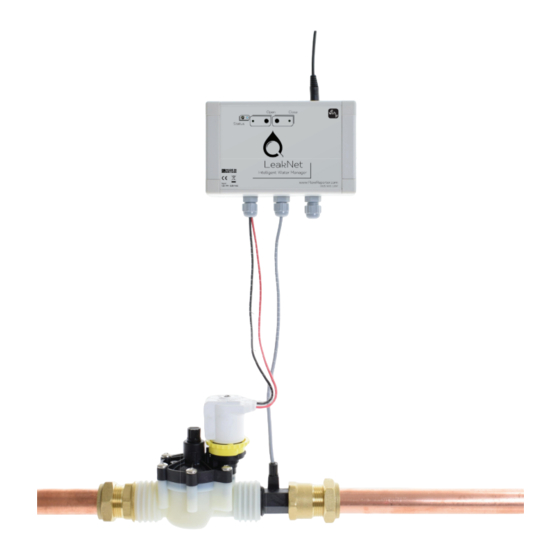
The LeakNet Base (pictured) can connect up to 4 meters, so it has the potential to measure the water fl ow through 4 different pipes, but most applications will involve just one. A valve can also be connected, but can be omitted if there is no wish to turn off the water supply. -
Page 5: Installation Guide
INSTALLATION GUIDE Overview Find the stopcock Decide where the LeakNet will be placed - this will normally be just after the stopcock, where the water enters the building. This will usually be coming up from the ground. Install valve and meter... -
Page 6: Item Checklist
INSTALLATION GUIDE Item checklist LeakNet Base front LeakNet Base rear Base screws and inserts With integrated circuit board. Wall mountable. To fasten the front of the Base to the rear of the Base. Power adaptor Water meter Valve 12V DC power adaptor. -
Page 7: Before You Begin
Before you begin The Base uses WiFi to communicate over the internet, and requires mains power. Before installing, decide where the LeakNet Base will be located: ● Within 10 meters of plumbed fi ttings, ● Within 10 metres of a 100-240V 50/60 Hz mains socket, ●... -
Page 8: Plumbing Instructions
INSTALLATION GUIDE Plumbing instructions Assemble all fi ttings. With pushfi t fi ttings, make sure the rubber washer is clean, and hand tighten. With compression fi ttings, use about 25 turns of PTFE tape around the thread, and then use a wrench to tighten. - Page 9 INSTALLATION GUIDE Plumbing instructions (continued) Turn the water supply off and drain the system (or up until the next stopcock downstream). Remove any dried paint on the pipes where the connections will be fi tted. Plumb in the fi ttings, making sure the arrows on the fi ttings match the direction of water fl ow.
-
Page 10: Wall-Mounting Instructions
Replace the LeakNet Base rear and screw into the wall plugs. The LeakNet Base and its power supply are not waterproof and should be installed in an appropriately safe place. The plug socket should remain accessible after installation in case of emergency. -
Page 11: Wiring Instructions
(1, 2, 3, 4) - it does not matter which one you use, as long as the correct configuration is recorded. If only one water meter is used, simply use terminal block 1. 4. Finally, place the LeakNet Base front onto the wall-mounted back, screw into place and use the plastic inserts to hide the screws. - Page 12 INSTALLATION GUIDE Wiring instructions Wiring guide for inputs and valves The wires will go to different positions in the LeakNet Base depending on the peripheral you are connecting. 3/4” water meter 1” water meter 2” water meter White - 5V...
- Page 13 INSTALLATION GUIDE Wiring instructions Record of installed inputs and valves Make a note of the inputs and valve here: Input # Type Name e.g. 1” meter Kitchen Valve type (circle) None Solenoid Motorised...
-
Page 14: Connecting To The Internet
INSTALLATION GUIDE Connecting to the internet These steps are to be performed by a computer or smartphone with WiFi capability. The entire process uses an internet browser. Login online Open up a new browser window and register for an account at www.FlowReporter.com. - Page 15 Once you have an account, log in and click “Register new Base”. and click “Register new Base”. Plug-in the LeakNet base and make sure the Plug-in the LeakNet base and make sure the “Status” light is blinking blue. If it isn’t, press and “Status”...
- Page 16 INSTALLATION GUIDE Connecting to the internet - in detail (continued) Return to the web browser and click “Next”. Return to the web browser and click “Next”. The screen should change to show the The screen should change to show the device scanning the area for other WiFi device scanning the area for other WiFi hotspots (if not, refer to the previous page).
-
Page 17: User Manual
USER MANUAL LeakNet Base On the front of the Base, you will see LEDs (lights), buttons and connections. Open Close button DC connector Open Close Status Status button button Screws Cable glands inserts... -
Page 18: Using The Buttons And Leds
USER MANUAL Using the buttons and LEDs Status To connect the Base to a new WiFi access point, use a sharp object, such as a pen, to hold down the “Status” button for around 4 seconds until the “Status” LED fl ashes dark blue. Open To open the valve, hold the “Open”... -
Page 19: Overview Of Software
USER MANUAL Overview of software LeakNet works in conjunction with a web application, which can be found at FlowReporter.com. The software is constantly being updated, so some of the following screens may change. For the most up-to-date documentation, please go to docs.FlowReporter.com in any internet browser. -
Page 20: Dashboard
USER MANUAL Dashboard After logging in, you will see a list of Base devices which you own: Temperature Base name Valve status input Click to view details and Status of valve confi gure connected to Base Click for graph Flow input Click for graph Below the list of owned Base devices, you will see a list of devices shared with you: Register new Base... -
Page 21: Base Device Confi Guration
USER MANUAL Base device confi guration Clicking a Base device from the dashboard will bring you to this screen: View log Click to view the history of valve status changes, and by which user Confi gure Base Toggle valve Click to open/close Click to modify inputs, Unique ID for Base their names, and... -
Page 22: Graphs
USER MANUAL Graphs After selecting a fl ow input, you will see a graph of the consumption for the current month: View Return to this screen Choose to view graph of real-time, day, Useful when navigating other pages month or year consumption Return to dashboard Choose the units you wish to view in -... -
Page 23: Device Settings
USER MANUAL Device settings After clicking device settings, you will see the following screen. Depending on your permissions, some sections and buttons may not be visible: Alerts Orange text shows minor alerts, red text show major alerts (where the water was shut off) - click to view detailed graph of event Archive Remove alerts from this page by... -
Page 24: Thresholds And Alerts
USER MANUAL Thresholds and alerts An alert is sent if either of the thresholds have been exceeded. Exceeding the “alert” threshold sends a minor alert, and exceeding the “shut off” threshold sends a major alert and shuts off the water. Here is an example situation where the fl ow of water begins at 17:30 and the thresholds are 1. -
Page 25: Sharing Access
USER MANUAL Sharing access To send access to another user, you must know their email address: Device name Recipient’s email Descriptive name so the recipient knows what they’re accessing The recipient will receive an email with a link to accept access to the device (if not, make sure to check the spam folder). -
Page 26: Specifications
Weight 230g Enclosure material Connectivity WiFi IEEE 802.11 b/g/n Power 12V DC 0.8A max Inputs Maximum number of inputs supported per LeakNet Base = 4. Meter specifications: Thread Nominal Nominal flowrate Pulses per litre (at diameter (DN) nominal flowrate) 3/4” BSP male 11mm 1.8 m3/h... -
Page 27: Maintenance
– 3 long flashes – 3 short flashes) which will help us determine the exact fault. If the problem persists, contact Quensus using the contact details on the back page of this manual. Cleaning A damp cloth is recommended for cleaning the LeakNet Base. -
Page 28: Technical Support
TECHNICAL SUPPORT Please contact Quensus if you require any technical assistance using the details below. Quensus, Strelley Hall, Nottingham NG8 6PE Tel.: +44/(0)115 906 1297 support@quensus.com www.quensus.com © Quensus 2018...
Need help?
Do you have a question about the LeakNet and is the answer not in the manual?
Questions and answers