
Subscribe to Our Youtube Channel
Summary of Contents for Termomont Temy Plus P 20
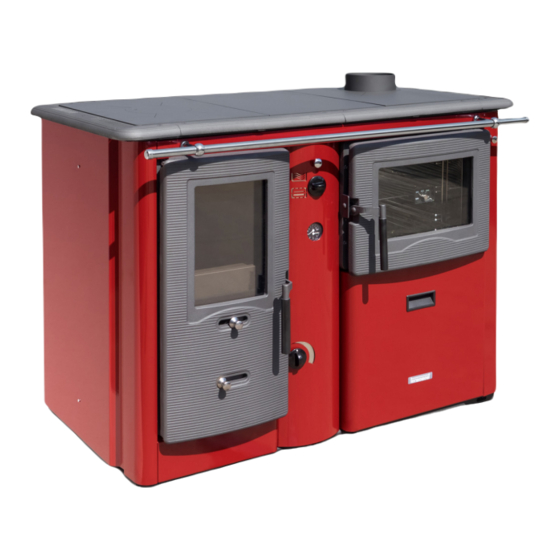
- Page 1 Temy Plus P 20 Residential cooker for solid fuels according EN 12815 Technical User Manual Customer service: Termomont d.o.o. Prhovačka bb 22310 Šimanovci tel. 022 480404, 022 480494 fax 022 480494 www.termomont.rs April 21, 2016...
-
Page 2: Table Of Contents
1.1 Boiler properties TEMY PLUS P 20 ......1.2 Boiler parts TEMY PLUS P 20 ....... -
Page 3: Technical Data
Technical data... -
Page 5: Boiler Properties Temy Plus P
Boiler properties TEMY PLUS P 20 Overall nominal power 20 KW Power transfered to the heating system 15 KW Overall width 1160 mm Overal height 890 mm Overall length 705 mm Necessary draught 14 Pa Flow 1" Return 1" Weight... -
Page 6: Boiler Parts Temy Plus P
Boiler parts TEMY PLUS P 20 Boiler part description: 1 Combustion chamber 2 Iron cast door 3 primary air 4 Sekundarni vazduh stakla 5 Iron cast grid 6 Ashtray 7 thermomanometar 8 secondary air control 9 Handle of flap for gas flue (water/oven) 10 handle of flap for gas flue second. -
Page 7: On Product
On Product TEMY PLUS P is a steel hot-water stove-boiler for central heating with cooking or baking in the same time, produced according to EN 12815. It is very easy to use and maintain. Boiler chamber is entirely made of steel (welded steel-plates), while the doors and the frame of the cooking plate is made of cast iron. -
Page 8: Primary, Secondary And Tertiary Air
Primary, secondary and tertiary air TEMY PLUS P has three air adjustment settings to make sure combustion process is perfect. Primary air is controled by the embedded automatic thermo-regulator mounted on the back side of the boiler: The setting of the primary air is located on the front side of the boiler. Secondary air is adjusted at the main combustion chamber door: Finally, tertiary air holes are located ath the back wall of the heating chamber (cannot be adjusted). -
Page 9: Directions For Storage And Transport
Directions for storage and transport Delivery form Boiler is shipped with plastic protection sleeve on a europallet. Boiler must be in its upright position all the time. The rotation of the boiler during the shipment or installation represents a serious risk and can lead to damaging the boiler. -
Page 10: Introductory Remarks
Introductory remarks The end user must follow the guidelines from this manual all the time. In contrary case the warranty won’t be acknowlidged. Pay strict attention that boiler valves are always open while boiler in use. Don’t forget to do a mechanical reset of the circulation pump at start of every heating season. Clean the boiler on a regular base. -
Page 11: Connecting The Boiler With A Closed Central Heating System
For open systems, working pressure depends on the overall height of the system and the open expansion vessel (1 bar for each 10 m is an estimate). After the filling process is done, it is obligatory to close the drain tap valve, close the water supply to the water-filling pipe and detach the water-filling pipe. -
Page 12: Installation Method 2
5.2.2 Installation method 2 To be used in the case of the boiler being positioned and installed at a lower level than the installed pipework and radiators. As shown on Figure, following elements are connected along the FLOW: 1. Automatic air vent 2. -
Page 13: Use Of Temperature Relief Valve With Obligatory Filling
Use of temperature relief valve with obligatory filling The temperature relief valve (shown below) must be present in the system. The valve must be installed by a qualified technician in accordance with the instructions given in the manual from the producer of the valve. -
Page 14: Boiler Operation
freeze during winter months). Please note that no additional items shall be connected to the open expansion vessel – espe- cially not valves. The size of expansion vessel is deducted from the following equation: = 0 07 water ( ) is the water volume in the entire installation. Diameter for the pipework of the expansion vessle water line should be round 25 mm. -
Page 15: Chimney
The water hardness may not exceed the recommended value. If you heat the boiler using coal, depending on the kind of coal and quality of combustion, boiler is to be cleaned at least every 30 days. Dirtier the boiler, the efficiency of the system is smaller. It is not allowed to extinguish the fire in the boiler artificially, it is forbidden to sprinkle the water inside the heating chamber. -
Page 16: Modes Of Operation
Modes of Operation Predominantly Heating or Baking Mode Depending on the chosen mode of operation TEMY PLUS P can perform in two modes. 1. Position 1: Predominantly Baking Mode: hot gases are directed to the oven. It is necessary to pull the flap handle (Position 3) to yourself in order to open the passage for the flue gases around the oven. -
Page 17: Overheat Protection Using The Thermostatic Valve (Closed System)
Cooking is possible in every working mode of the stove-boiler. Before any operation it is necessary to clean the boiler and check the pressure of the entire system. Overheat protection using the thermostatic valve (closed system) TEMY PLUS P has an embedded heat exchanger inside the heating chamber (position 12) which has to be connected to the thermostatic overheat protection valve (such as Danfoss BVTS, Caleffi... -
Page 18: Boiler Cleaning And Maintenance
First connect the sensor (male thread 1/2”) on the marked position on the boiler - female thread 1/2” Now connect the cold water supply to the valve - female thread 3/4”, then connect the valve to the position 1 (cold water entrance), the boiler should have the prepared reduction 3/4”-1/2” Connect the hot water exit toward the sewerage.
Need help?
Do you have a question about the Temy Plus P 20 and is the answer not in the manual?
Questions and answers