
Related Manuals for ES AWH9-V5+

Summary of Contents for ES AWH9-V5+
-
Page 1: Heat Pump
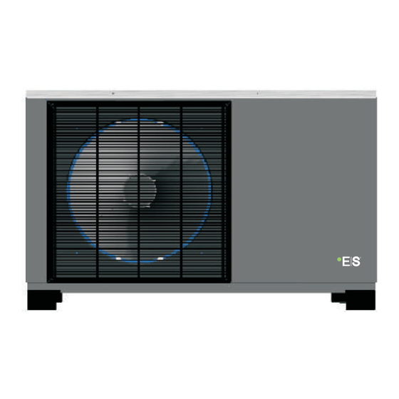
AWH9/11-V5+ MBG series DC Inverter Air to Water Heat Pump User’s manual U s e r ’ s m a n u a l Before operating this product, please read the instructions carefully and keep this manual for future use. -
Page 3: Table Of Contents
Catalogue 1. Before use 1.1 Safety precautions 1.2 Working principle 1.3 Main components 1.4 Specifications 2. Installation 2.1 General application system introduction 2.2 Tools needed 2.3 Installation of the indoor control unit 2.4 Installation of the monoblock unit 2.5 Accessories 2.6 Wiring Installation of safety valve kit Water pipe connection... -
Page 4: Before Use
1. Before use 1.1 Safety precautions The following symbols are very important. Please be sure to understand their meaning, which concerns the product and your personal safety. Warning Caution Prohibition User Manual The installation, dismantlement To avoid electrical shock, make Be sure to read this manual before sure to disconnect the power and maintenance of the unit must... - Page 5 1. Before use Fuse Steel Copper When the power cord gets loose Please select the correct fuse or Be aware fingers might be hurt by or damaged, always get a qualified breaker as per recommended. Steel the fin of the coil. person to fix it.
-
Page 6: Working Principle
1. Before use 1.2 Working principle Power supply Four-way vavle Compressor Water Outlet Pressure Three-way valve check valve Water pump Fan motor Water inlet Filter Refrigerant Filter T-connector Heat exchanger Heating Cooling... -
Page 7: Main Components
1. Before use 1.3 Main components 1.3.1 Indoor control unit Cable gland Pressure Relief Valves Water inlet Water outlet Door Electric box Electric box cover Operation panel Water pump... - Page 8 1. Before use 1.3.2 Monoblock unit AW9-V5+ AW11-V5+...
-
Page 9: Specifications
1. Before use 1.4 Specifications Type of Product DC Inverter Air to Water Heat Pump Unit Model AWH9-V5+ AWH11-V5+ Power Supply V/Hz/Ph 220-240/50/1 Refrigerant R410A/2.45 R410A/1.9 Max. Heating Capacity (1) 10.10 11.5 C.O.P (1) 4.03 3.82 Heating Capacity Min./Max.(1) 4.33/10.10 4.67/11.5 Heating Power Input Min./Max.(1) 975/2153... - Page 10 1. Before use Type of Product DC Inverter Air to Water Heat Pump Unit Model AWH9-V5+ AWH11-V5+ Type Plate Heat Exchanger Stainless Steel+Copper Material Water Side Heat Exchanger Water Pressure Drop Piping Connection Inch G1” Min. Water Flow 0.26 0.31 Allowable Water Flow Rated Water Flow 0.43...
-
Page 11: Installation
2. Installation 2.1 Application system introduction Application 1: Sanitary hot water 40~50℃ Hot water outlet 热水出水口G1" AH-200L G1" G1" City water inlet 生活热水补水口 G1" Drawing Name Ball valve One way valve Filter Application 2: Floor heating system To city water D e 32 Floor heating De3 2... - Page 12 2. Installation Application 3: Heating and cooling system Fan coil unit To city water De32 De32 Floor heating De25 distribution system De25 De32 De40 UPS 25/80 Drain outlet 30L buffer tank De32 De40 Water discharge outlet De25 Name Name Drawing Drawing Refrigerant pipe Ball valve...
-
Page 13: Tools Needed
2. Installation 2.2 Tools needed Most people already have the tools needed for installation: spirit level, pencil, crosshead screwdriver, drill, 8 mm. concrete drill bit, detection drill, square, tape measure or ruler, tape width 65 mm, hole saw about 80 mm (deviation in size may occur), knife and two adjustable spanners or pliers (and possibly torque wrench). - Page 14 2. Installation 2.3.2 Installation Indoor control unit should be mounted on the wall as per procedures below: 1) Take out the expansion bolts and mounting board from accessory and put the mounting board on the wall horizontally; Mark on the wall the location for bolts through the holes on mounting board. 2) Drill holes with proper diameter for expansion bolts.
-
Page 15: Installation Of The Monoblock Unit
2. Installation 2.4 Installation of the monoblock unit 2.4.1 Installation notes 1) The monoblock unit can be located in a open space, corridor, balcony, and roof. 2) The monoblock unit shall be placed in dry and well-ventilated environment; If the monoblock unit is installed in humid environment, electronic components may get corroded, or short-circuited because of... - Page 16 2. Installation 2.4.2 Installation User can either use the dedicated mounting bracket from the supplier, or prepare a suitable bracket for the unit installation. Make sure the installation meets following requirements: 1) The unit must be installed on flat concrete blocks, or a dedicated mounting bracket. The bracket should be able to support at least 5 times of unit’s weight.
-
Page 17: Accessories
2. Installation 2.5 Accessories Accessories below are delivered together with the product . Please check in time. If there is any shortage or damage, please contact local distributor. Quantity Name Picture User’s manual User Manual Drain pipe Safety valve kit Quantity Name Picture... -
Page 18: Wiring
2. Installation 2.6 Wiring ◆ It is recommended to use a suitable circuit breaker for the heat pump; ◆ The power supply to the heat pump unit must be grounded. ◆ The wiring should be done by professional person. ◆ The wiring should be comply with the local industry regulation. - Page 19 2. Installation Before wiring, open the indoor control unit front panel and take off the electronic box cover. 1) Heat pump unit power supply Get a power cable in suitable length that complies to the local safety regulations. A. Insert one end of this cable through the cable gland on bottom of the indoor control unit, and connect it with heat pump power supply terminals (G, N, L).
- Page 20 2. Installation 2) Monoblock unit power supply. Get a power cable in suitable length that complies to the local safety regulations. A. Insert one end of this cable through the cable gland on back of the outdoor control unit, and connect it with heat pump power supply terminals (G, N, L). B.
- Page 21 2. Installation 3) Aluminum foil electric heating piece power cable between indoor control unit and monoblock unit Prepare a 3 cores power cable with suitable length that complies the local safety regulations, Shown as "Outdoor unit " on wiring diagram For more solid connection, for that cables that need to be connected with terminals:.
- Page 22 2. Installation Warning. Electric heater for water lines inside outdoor cabinet must be attached. Pipe insulation must be able to hold 120℃. Separate power supply to heater. Water pipe connected between monoblock unit and house (water pipe in between should not longer than 50cm.) Copper or Steel water pipe,28mm...
- Page 23 2. Installation 4) Signal cable between indoor control unit and monoblock unit 10M communication cable is packed in accessories bag. corresponding with each other A. Insert one end of this cable through the cable gland on top of the indoor control unit, and connect this cable to A, B, on terminal block.
- Page 24 2. Installation 5) Sensor cables Take all sensors and communication cables out from the accessories bag. Connect the sensors together with the quick connectors on communication cables. After done, insert communication cables (the end without quick connector) that have no quick connector through cable gland, and connect them to the correspondent terminals on terminal block.
- Page 25 2. Installation Install the electric box cover on indoor control unit and electric box cover on monoblock unit back, and close the door of indoor control unit.
-
Page 26: Installation Of Safety Valve Kit
2. Installation 2.7 Installation of safety valve kit 1) Install the safety valve kit to the connector on top of indoor control unit. 2) Connect the drainage pipe to safety valve outlet. -
Page 27: Water Pipe Connection
2. Installation 2.8 Water pipe connection After installing the unit, please connect the water inlet and outlet pipe according to the local regulations Please carefully select and operate the water pipe. After connection, the water piping should be pressure tested, cleaned before use. 1) Filter A mesh filter must be installed in front of the water inlet of the unit and water tank, to keep the water quality and collect impurity contained in the water. -
Page 28: Test Run
2. Installation 2.9 Test run After installation finished, please fulfill the water system with water and purge out air in the system before start-up. Before start-up Before the unit starts up, a certain number of verifications must be performed on the installation to ensure that the unit will operate under the best possible conditions. -
Page 29: Usage
3. Usage 3.1 Introduction of wired controller Timer ON/OFF Confirm MODE Up-Regulation Down-Regulation Symbol Function Explanation Working mode When heating mode is selected, symbol is Symbol shown in display when selected, Heating mode shown in the display flickers when activated When cooling mode is selected, symbol is Symbol shown in... - Page 30 3. Usage Explanation Symbol Working mode Function Indicates the current working level, Compressor If symbol is "ON" compressor is working “low range30-46”, "middle range47-65", indicator "high range66-100” Shows time when unit is "ON", Shows Clock and parameter menu and group Clock or parameter parameter groupe or -number when unit indicator...
-
Page 31: Parameter Setting Overview
3. Usage 3.2 Parameter Setting Overview Operation Page in Default factory Unit Statue Item Sub-menu Level the menu settings Under Clock Time None User 00:00 User Temp. Setting Hot water/Heating/Cooling Hot water, heating, cooling, hot Working Mode water+heating, hot water+cooling, User heating+cooling, hot water+heating +cooling... - Page 32 3. Usage All the units sensor values (temperatures) and information of current running statue (compressor speed, voltage and current) can be red and checked via operation panel in both ON/OFF statue. Press buttons for 5 seconds in main interface, to activate the menu of current running statue. Press buttons to check all working status in sequence in accordance to below list.
- Page 33 3. Usage Default factory Operation Page in Item Sub-menu Unit Statue settings Level the menu Ambient temp. to start heating ° Check in Ambient temp. to start cooling 25° Temperature ON/OFF, Set User Parameter in OFF Shifting priority 100 ° 20°...
- Page 34 3. Usage Default factory Page in Operation Item Sub-menu Unit Statue settings the menu Level Unit Motorized 3-way valve 120 sec Advanced Switching Time Installer Setting Group Heating Operation Motorized 1 same as cooling operation 3-way valve Direction Anti-Legionella Set Temperature Anti-Legionella Duration 30 min.
- Page 35 3. Usage Page in Operation Default factory Unit Statue Item Sub-menu the menu Level settings Under Ambient Temp. 1 Ambienttemp 1 Vs Water Temp. 1 Ambient Temp. 2 Ambienttemp 2 Vs Water Temp. 2 Ambient Temp. 3 Advanced Ambienttemp 3 Vs Water Temp. 3 Installer Setting Group Ambient Temp.
-
Page 36: Basic Operation
3. Usage 3.3 Basic Operation 【 】 ON/OFF When the unit is OFF press to turn on the unit The unit will work in its last working mode Press again to turn off the unit. OFF: The unit is OFF when it is fed with power. -
Page 37: Room Temperature Control
3. Usage 【 】 Room Temperature Control When unit is ON, keep on pressing "M" to switch the control of cooling and heating operation between room temperature control and water temperature control mode. When in water temperature control mode, "Water Temp." will be shown on the screen; When in room temperature control mode, "Water Temp."... - Page 38 3. Usage 【 】 Time&Timer Setting Timer function allows you to control different working modes at spesific hours during a 24 hour periode, for even more energy savings. For example you can turn off hot water production in the daily hours you don’t use this. In the selected periode unit will not produce hot water even hot water is selcted as working mode in your application.
- Page 39 3. Usage For example, parameter 00 is to set the ON/OFF of complete timer function (if it is set to OFF, following parameters 01~08 will be invalid). When setting for this parameter is activated, use to adjust the value. For example, parameter 01 is the ON time for hot water function. When setting for this parameter is activated, press to adjust the setting in hours;...
- Page 40 3. Usage Heating/Cooling Timer: Range Default Value Meaning Parameter No. Heating/Cooling Timer ON-1 00 00-23 59 00 00 Heating/Cooling Timer OFF-1 00 00 00 00-23 59 Heating/Cooling Timer ON-2 00 00 00 00-23 59 Heating/Cooling Timer OFF-2 00 00-23 59 00 00 These parameters are used for setting the ON/OFF timer for heating or cooling operation.
- Page 41 3. Usage For example, if the setting is made like below: Meaning Value Parameter No. Normal Shower Time (for unit with 20 00 heat recovery function only) If at time 19:00 in the day, shower water is still not enough for shower, unit will activate standard hot water operation, instead of using recovered heat to heat up the shower water.
- Page 42 3. Usage Meaning of all readings: Item Meaning Item Meaning System 2 evaporating pressure DHW Set Temp System 2 condensing pressure Heating Set Temp Cooling Set Temp System 2 EEV position System 1 indoor coil temperature Room Set Temp System 1 voltage (V) Ambient temperature System 1 current (A) Hot water temperature...
- Page 43 3. Usage Temperature Parameter under basic operation level can be set in "OFF" mode only. Value of the Press "SET"+"M" for parameter 5 seconds, Parameter will shown on the display Sequence of the parameter Press or to check parameter values for each paramter in sequence.
- Page 44 3. Usage List of parameters Range Default Value Meaning Parameter No. Domestic Hot Water Restart Based 0 - 10 (in ℃) On Water ∆T Heating Restarts Based On Water ∆T 0 - 10 (in ℃) Cooling Restarts Based On ∆T 0 - 10 (in ℃) 0(via.
- Page 45 3. Usage If cooling port receives the signal, the system switches to cooling; If heating port receives the signal, the system switches to heating. When neither port receives the signal, the system stays in standby mode. Note: If system has a very big buffer tank for both cooling and heating operation, please pay special attention to set "Auto"...
- Page 46 3. Usage Meaning Range Default Value Parameter No. Heating Curve Function 0(invalid), 1(valid) Heating Curve means let the system adjust the outlet water temperature based on the ambient temperature by continually monitoring and adjusting in opposite direction with the current ambient temperature levels according to a pre-set curve, to optimum comfort levels based on the changing heat demand,insulation levels,etc.
- Page 47 3. Usage (TSh) (Tsha) T(Ta) (Ta) As shown here, actual set water temperature (TSha) is calculated according to actual ambient temperature (Ta), according to this created curve.
-
Page 48: Advanced Setting
3. Usage Advanced setting Advanced setting is opened to installer or professional customer. It contains more functions and setting that can maximum the comfort and efficiency of the system.You need to enter the correct password to activate "Advanced Setting": 2.Press 5 seconds 3."----"... -
Page 49: System Setting
Port On PCB Relay Output 3-way valve (Cooling/Heating Port) 3-way valve (Hot Water Port) Auxiliary Heater Heating Back-up Heater IRES Domestic Hot Water Back-up Heater ES+FS PUMPH Heating Distribution System Pump ES+HS PUMPC Cooling Distribution System Pump ES+CS Unit Circulation Pump... - Page 50 External ON OFF Switch An external Close/Open signal from other control devices can be connected to the ES and GND port shown on the below picture on indoor PCB, to switch ON/OFF the working of complete heat pump unit, if this parameter is set to 1: When the input external signal is "close"...
- Page 51 3. Usage Meaning Range Default Value Parameter No. Cooling Buffer Tank 0(no), 1(yes) This parameter is used to set whether the system has a buffer tank for cooling operation. It is more related to the control of "circulation pump for cooling system". If there has no buffer tank included in the cooling system, "circulation pump for cooling system"...
- Page 52 3. Usage Meaning Range Default Value Parameter No. Stop/Speed down ΔT based on set 2-10 temperature in heating/cooling Max Allowed Duration For 10-60(in minutes) Min Compressor Speed Stop/Speed down ΔT based on set temperature in heating/cooling: Steop ΔT based on set temperature in heating/coolingmeans after the unit heat/cool the water (or air, if in room temperature control mode) above/below set temperature over the set delta T here, unit stops.
- Page 53 3. Usage Range Meaning Default Value Parameter No. Heating Circulation Pump Start 20 - 50 (in ℃) Temperature Heating Cirulation Pump Stop 18 - 50 (in ℃) Temperature Cooling Circulation Pump Start 5 - 20 (in ℃) Temperature Cooling Cirulation Pump Stop 5 - 20 (in ℃) Temperature 0 (Alway ON), 1 - 600(With...
- Page 54 3. Usage Range Default Value Meaning Parameter No. 0 (Alway ON), 1 - 600(With Unit Motorized 3-way valve power for the set time, in Switching Time seconds) 0 (Same as Hot Water Heating Operation Motorized 3-way Operation), 1(Same as valve Direction Cooling Operation) Parameter A8 is used to set the type of the motorized 3-way valve used to switch the direction of water flow in different working modes.
- Page 55 3. Usage Range Default Value Meaning Parameter No. Anti-freezing Function 0(invalid), 1(valid) Anti-freezing Starting Ambient 5 - 10 (in ℃) Temperature--Primary Anti-freezing Starting Ambient 0 - 4 (in ℃) Temperature--Secondary Anti-freezing Ending Ambient 0 - 10 (in ℃) Temperature--Secondary Anti-freezing Starting Water 0 - 10 (in ℃) Temperature--Secondary Anti-freezing Ending Water...
- Page 56 3. Usage Meaning Range Default Value Parameter No. Manual ON/OFF of Heater in Hot 0(invalid), 1(valid) Water Mode If heat pump unit meets a failure, extra heating source (unit "Auxiliary Heater" or "Backup Heating Source For Hot Water Mode" can be manually switched ON for heating up the shower water by set "Manual ON/OFF of Heater in Hot Water Mode"...
- Page 57 3. Usage Range Default Value Meaning Parameter No. Backup Heating Source For 0(no), 1(yes) Heating Mode Priority Of Backup Heating Sources 0(lower), 1(higher) For Heating Mode (Compared With Unit Auxiliary Heater) Accumulated Value between operation 0 - 600 time VS set temp. for Heating Mode If there has a "Backup Heating Source For Heating Mode"...
- Page 58 3. Usage These parameters are valid only for the units with heat recovery function. For the unit without this function, "Heat Recovery Function" should always set to 1 (invalid). If it is set to ON, unit will try to heat up the hot water by recover the wasted heat in heating and cooling operation. It will turn ON heat recovery circuit if actual hot water temperature is "Hot Water Restart Based On ∆T in Heat Recovery Operation"...
-
Page 59: Failure Code
3. Usage 3.5 Failure code When unit is in ON/OFF mode and has some failure, which part has this failure and the failure code will be shown as follows: 00: indoor unit 01: compressor system 1 Failure code or 02: compressor system 2 protection code 03: Wired controller... -
Page 60: Error Code
3. Usage 3.6 Error code Outdoor Unit Failure Codes. 01 or 02 stands for different compressor systems. For sigle compressor system, it indicates the failure of outdoor unit no matter 01 or 02 is shown. Possible Reasons And Solutions Type Code Failure Unit worki ng statue... - Page 61 3. Usage Outdoor Unit Failure Codes. Type Failure Unit working statue Code Possible Reasons And Solutions This is a protection caused by outdoor coil temperature too high. Check whether air circulates fluently in outdoor Outdoor evaporator coil temp. unit, air flow is too small, ambient temperature is too 01(02) P9 Comprssor stops sensor protection...
- Page 62 3. Usage Outdoor Unit Failure Codes. Possible Reasons And Solutions Type Code Failure Unit worki ng statue Preserved for monoblock unit only. Please check Comprssor stops 01(02) F8 Water flow switch failure the statue of water flow switch. Speed of DC fan (FAN 2) can't reach the required Comprssor speed down value or no feedback signal.
- Page 63 3. Usage Outdoor Unit Failure Codes. Possible Reasons And Solutions Type Code Failure Unit worki ng statue Check the communication cable between outdoor power Outdoor power PCB and driver Comprssor stops PCB and driver PCB. Check whether outdoor power PCB 01(02) E2 PCB communication failure or driver PCB is broken.
- Page 64 3. Usage Indoor Unit Failure Codes Possible Reasons And Solutions Type Failure Unit working statue Code 1.Cooling operation is Check whether ambient temperature sensor is open, limited. 2.Cooling and short-circuit or value drifts too much. Replace it if heating auto-switch is necessary.
- Page 65 3. Usage Indoor Unit Failure Codes Failure Unit worki ng statue Possible Reasons And Solutions Type Code If system water flow rate too small protection, 00P7, happens over 3 times in certain periof of time, unit Too small water flow rate 00 Ec gives this failure code and can only be reset by Compressor stops...
- Page 66 3. Usage Indoor Unit Failure Codes Type Failure Unit working statue Code Possible Reasons And Solutions Compressor of system 1 speed stops. If this 1.Check whether set temperature for cooling is too low; failure doesn't recover whether system has too small water flow rate; check automatically after System 1 indoor anti-freezing water system especially the filter.2.Check whether...
- Page 67 3. Usage Indoor Unit Failure Codes Type Code Failure Unit working statue Possible Reasons And Solutions When unit is working in defrosting, if water outlet temperature is too low, water may freezing up in plate heat exchanger and damage the plate heat exchanger.
- Page 68 3. Usage Protection preserved for other models(Check below part if unit stops without any failure information in cooling or defrosting mode): Type Code Failure Unit working statue Possible Reasons And Solutions Water flow switch If there has no water flow switch installed in LED light on protection (preserved outdoor unit, please check whether "LOW"...
-
Page 69: Maintenance
4. Maintenance 4.1 Attention 1) The user mustn't change the structure or wiring inside the unit. 2) The service and maintenance should be performed by qualified and well-trained technician. When the unit fails to run, please cut off power supply immediately. 3) The smart control system can automatically analyze various protection problems during daily use, and display the failure code on the controller. - Page 70 4. Maintenance This system uses R410A refrigerant. It is strictly forbidden to charge any refrigerant other than R410A into the system. There must be no air in the refrigerant circulation, because air will cause abnormal high pressure, which will damage the gas piping and lower heating or cooling efficiency. If the refrigerant leaks inside the house, please keep windows open for few minutes even R410A refrigerant do no harm to health.
-
Page 71: Condenser Coil
4. Maintenance 4.5 Condenser coil The condenser coils do not require any special maintenance, except when they are clogged by paper or any other foreign objects. Cleaning is by washing with detergent and water at low pressure, and then rinsing with clean water: 1) Before cleaning, make sure the unit is off. - Page 72 4. Maintenance 4.6.2 Replacement of water pump 1) Cut off the power supply, open the front panel and take off the electric box cover. Disconnect quick connector of water pump power cable, and pull out the signal cable connected to the indoor control PCB. Cut water supply to the unit, and drain out water in the monoblock unit away.
- Page 73 4. Maintenance 4.7 Service of monoblock outdoor unit 4.7.1 Maintenance of controller 1) Cut off the power supply, take off the top cover of the unit. Take off the electric box cover. Do necessary maintenance work to the controller of monoblock outdoor unit . Top cover Electric box cover...
- Page 74 4. Maintenance Replacement of fan motor 4.7.2 take off screws of the front grill. 1) Cut off the power supply, Use a wrench to loosen the nut for fan blade and take out the fan blade. Take off the screws of fan motor. Plug out power cable for fan motor from PCB.
- Page 75 4. Maintenance Cable connected to fan motor capacitor...
- Page 76 4. Maintenance Replacement of bottom plate heater 4.7.3 1) Cut off the power supply, follows 4.7.2 to take out the fan blade. Take off the fixture of bottom plate heater(see picture 1). Disconnect the quick connector for bottom plate heater and take the heater out (see picture 2). Put a new bottom plate heater back, and connect it to the quick connector(see picture 3).
-
Page 77: Trouble-Shooting
4. Maintenance 4.8 Trouble shooting Failure Cause Solution 1. No power supply 1. Check the power supply 2. Check if it's open circuit or if the unit is earthed. 2. Fuse is broken or circuit Then change a fuse and reset the breaker, check if the breaker is disconnected circuit is stable or the connection is well. - Page 78 4. Maintenance The following phenomenon may not be problems of unit itself. Please contact with a professional maintenance staff for help. Number Failure Solution When the unit restarts, the compressor will start 3 minutes later (self-protection of compressor), please check if the circuit breaker is disconnected, The unit is not running and if there is normal power supply for the wire controller.
-
Page 79: Attached Drawing
5. Attached drawing 5.1 Outlines and dimensions —— Indoor control unit Unit:mm... - Page 80 5. Attached drawing —— Monoblock unit AW9-V5+ 1053 1065...
- Page 81 5. Attached drawing —— Monoblock unit AW11-V5+ Unit:mm 1204 1215...
-
Page 82: Exploded View
5. Attached drawing 5.2 Exploded view —— Indoor control unit Name Front panel Wire controller kit Electric box cover Indoor PCB Electric system Water pump kit Pressure relief valve kit Water flow switch Bracket... - Page 83 5. Attached drawing —— Monoblock unit AW9/11-V5+ Name Name Evaporating Coil Temp. Sensor Low Pressure Sensor Compressor Crankcase Heater Coil for Four-way Reserving Valve Drain Pan Heater 4-way Reserving Valve Compressor Suction Temp. Sensor Outdoor PCB Board Compressor Compressor Discharge Temp. Sensor Plate Heat Exchanger Module Assembly Condensing Coil Temp.
-
Page 84: Wiring Diagram
5. Attached drawing 5.3 Wiring diagram —— Indoor control unit AWH9/11-V5+... - Page 85 5. Attached drawing —— Monoblock unit AWH9/11-V5+...
- Page 86 Thank you for choosing our quality product. Please read this manual carefully before use and follow the instructions to operate the unit in order to prevent damages on the device or injuries to staff. Specifications are subject to change with product improvements without prior notice.
Need help?
Do you have a question about the AWH9-V5+ and is the answer not in the manual?
Questions and answers