Table of Contents
Advertisement
Quick Links
Advertisement
Table of Contents

Summary of Contents for North Star 163cc
- Page 1 163cc Power Trowel Owner’s Manual WARNING: Read and understand all instructions, warnings, and cautions before using this product. Failure to follow the instructions, warnings, and cautions may result in serious personal injury and/or property damage. Item #49391 SAVE THESE INSTRUCTIONS...
- Page 2 Thank you very much for choosing a North Star product! For future reference, please complete the owner’s record below: Serial Number/Lot Date Code: ________________________________ Purchase Date: ____________________________________________ Save the receipt, warranty, and this manual. This Power Trowel is designed for certain applications only. Northern...
-
Page 3: Table Of Contents
Table of Contents Intended Use ............................4 Technical Specifications ........................4 Important Safety Information ....................... 5 Specific Operation Warnings ....................... 8 Main Parts of Power Trowel ....................... 10 Assembly Instructions ........................11 Before Each Use ..........................14 Operating Instructions ........................15 Start the Engine .......................... -
Page 4: Intended Use
39 x 67 x 39 (in) (1000 x 1700 x 1000 (mm)) Working Blade Diameter 36 (in) (914 mm) Number of Blades 0 – 15 ° Pitch Range 60 – 130 rpm Trowel Speed ² Efficiency 2152(ft Engine Honda GX-160 / 163cc Page 4 of 33... -
Page 5: Important Safety Information
Important Safety Information The warnings, cautions, and instructions in this manual cannot cover all possible conditions or situations that could occur. Exercise common sense and caution when using this tool. Always be aware of the environment and ensure that the tool is used in a safe and responsible manner. ... - Page 6 PERSONAL SAFETY Stay alert, watch what you are doing, and use common sense when operating the Power Trowel. Do not use the Power Trowel while you are tired or under the influence of drugs, alcohol, or medication. Dress properly. Do not wear loose clothing, dangling objects, or jewelry. Keep your hair, clothing and gloves away from moving parts.
- Page 7 POWER TROWEL USE AND CARE Do not force the Power Trowel to perform an operation other than its intended use. Power Trowels do a better and safer job when used in the manner for which they are designed. Plan your work, and use the correct Power Trowel for the job.
-
Page 8: Specific Operation Warnings
Specific Operation Warnings To avoid fatal accident Stop the engine before refueling and be careful not to spill fuel during the refueling. Spilled fuel may ignite causing a fire. Do not refuel the engine near flammable objects to avoid fire. ... - Page 9 gloves, safety shoes, safety glasses and mask before operating the power trowel. Do not insert your hand or finger between pulley cover and engine during the operation, it may break your hand or finger. Do not transport the power trowel by motor vehicle with fuel in the trowel’s fuel tank. ...
-
Page 10: Main Parts Of Power Trowel
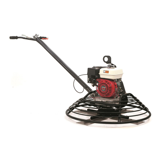
Main Parts of Power Trowel Throttle Lever Blade Pitch Handle Engine Stop Switch Handle Belt Cover Blade Holder Blade Safety Ring Engine Stop Switch Engine Fuel Cap Engine Air Filter Engine Muffler Page 10 of 33... -
Page 11: Assembly Instructions
Assembly Instructions Note: To allow clearance to adjust the blade pitch in step 5, support the safety ring of the screed on some bricks between the blade tips so the blade pitch can be changed during testing of this feature. 1. - Page 12 3. Turn the Blade Pitch Handle counter-clockwise. 4. Continue to turn the Blade Pitch Handle counter-clockwise until the Adjust Screw Nut is at the bottom. (The Adjust Screw Nut is the silver piece in the bottom center of the green piping in the picture at right. Also see Handle parts diagram, item 19.) 5.
- Page 13 8. Check that the engine throttle lever (silver lever in picture) is at its idle position (fully left in picture) then attach the Accelerator Cable position (3) and wire (4). ④ ③ 9. Assemble the Air Filter Element and the Air Filter Cover. 10.
-
Page 14: Before Each Use
Before Each Use Engine Recommended Fuel The trowel engine requires fresh, clean, regular, unleaded gasoline . Fuel containing water or dir t will damage the fuel system. Consult to engine owner’s manual for complete fuel specifications. DANGER: Adding fuel to the tank should be done only when the engine is stopped and has had an opportunity to cool down to avoid a risk of an explosion or fire from a fuel spill. -
Page 15: Operating Instructions
Operating Instructions Operators must be trained in the use of the power trowel and maintain practiced skill. It is dangerous to operate this machine improperly or by an untrained person. An operator should read and understand the manual and follow its directions. This power trowel is equipped with an engine stop switch. -
Page 16: After Each Use
After Each Use Cleanup Check that the compactor engine is turned off and cooled before attempting any maintenance, cleaning, or inspection. Performing maintenance on an operating compactor can cause injury. 1. Wash the trowel with water immediately after use so concrete does not dry on the machine, taking care to not get the engine or electrical controls wet. -
Page 17: Maintenance
Maintenance Check that the compactor engine is turned off and cooled before attempting any maintenance, cleaning, or inspection. Performing maintenance on an operating compactor can cause injury. Maintain the Power Trowel by adopting a program of conscientious repair and maintenance in accordance with the following recommended procedures. -
Page 18: Change V-Belt
Change V-Belt Check that the power trowel engine is turned off and cool before attempting to change the V-belt. Changing the V-belt while the trowel is still hot or operating will cause injury. 1. Remove the bolts to remove the belt cover. The pictures below show the front and rear brackets that hold the black belt cover to the engine. -
Page 19: Change Blades Set
Change BLADES SET Check that the power trowel engine is turned off and cool before attempting to change the V-belt. Changing the V-belt while the trowel is still hot or operating will cause injury. Supplies: Blade Set, Bolt for Blade Set, Plain Washer for bolt, Spring Washer for Bolt, 1/2”... - Page 20 4. Loosen the outside bolt with the 1/2 in. wrench (Fig. 3). 5. Remove the blade. 6. Clean the lower part of the blade arm of foreign debris. 7. Place the new blade under the blade arm and align the bolt holes on each. 8.
- Page 21 9.2 Keep the torque wrench setting at 13.02 ft-lb and tighten the outer bolt (Fig. 5). 9.3 Reset the torque wrench to 14.46 ft-lb (19.62 N-m or 200 kgf.cm) and tighten the outer bolt again. 9.4 Keep the torque wrench setting at 14.46 ft-lb and tighten the inner bolt a second time. 9.5 Set the torque wrench to 17.36 ft-lb (23.54 N-m or 240 kgf.cm) and tighten the inner bolt for the third time.
-
Page 22: Parts Diagram
Parts Diagram Handle Page 22 of 33... - Page 23 Parts No. Description Q’TY Dimension RG-003 Plastic Cover QSC-M4*8 Screw M4x8 QWS-PM4 Plate Washer TSA-01 Throttle Assy. QNT-NM4 Nylock Nut W436F-001 Handle WA PAS-02 Stop Switch(release bar Type) 436F-01-001 Adjust Knob QSP-5X50 Spring Pin 5x50 QBR-51104 Bearing QBL-M6X10 Bolt M6x10 436F-01-004 Aluminium Guide QWS-WM19...
-
Page 24: Blade
Blade Page 24 of 33... - Page 25 Parts No. Description Q’TY Dimension QWS-SM10 Spring Washer QWS-PM10 Plate Washer 436F-02-005B Press Plate Cap QBR-6009 Bearing 6009 436F-02-006B Press Plate Cap QBL-M10X20 Bolt M10x20 QBL-BBM10X35 Round Head Bolt M10x35 QNT-TM10 Thin Nut QBL-SHM10X30 Square Head Bolt QBL-7/16X11/2 Bolt 7/16*3/2L QWS-SM8 Spring Washer QWS-PM8...
-
Page 26: Gear Box
Gear Box Page 26 of 33... - Page 27 Parts No. Description Q’TY Dimension 436F-03 Gear Box Assembly QNT-NM10 Nylock Nut QWS-SM10 Spring Washer QWS-PM10 Plate Washer QBL-M6X16 Bolt M6x16L QRV-M8 Release Valve 436F-03-004 Big Cover 436F-03-005 Gasket of Big Cover QBL-FHM10x25 Flat Socket Head Bolt M10x25 QWS-SSM10 Washer QBR-30305 Bearing 30305...
-
Page 28: Safety Ring
Safety Ring Page 28 of 33... - Page 29 Parts No. Description Q’TY Dimension QWS-SM8 Spring Washer GX160 Engine GX-160 W436F-005 Hook Lift (Option) QBL-SHM8X20 Socket Head Cap Bolt (Option) 436F-04-013 Clutch Busing CA-01 Clutch 90-1 CA-01-004 Face Plate 90-2 QBL-AM8x16 Set Screw M8x16 90-3 CA-01-005 Clutch Spring 90-4 CA-01-003 Shoe Weight 90-5...
-
Page 30: Troubleshooting
Troubleshooting To avoid risk of severe injury, turn off the engine and allow it to cool before performing any maintenance, cleaning, or inspection. Check the list below before addressing the problems to servicing personnel including local dealer. If th e problem continues after the following troubleshooting, call your local dealer for future assistance. Problem Possible Cause Solution... -
Page 31: Replacement Parts
Replacement Parts For replacement parts and technical questions, please call Customer Service at 1-800-222-5381. Not all product components are available for replacement. The illustrations provided are a convenient reference to the location and position of parts in the assembly sequence. ... -
Page 32: Limited Warranty
Northern Tool and Equipment Company, Inc. ("We'' or '"Us'') warrants to the original purchaser only ("You'' or “Your”) that the North Star product purchased will be free from material defects in both materials and workmanship, normal wear and tear excepted, for a period of two years from date of purchase with the Honda GX engine having a period of three years from date of purchase. - Page 33 Distributed by: Northern Tool and Equipment Company, Inc. Burnsville, Minnesota 55306 www.NorthernTool.com Made in Korea Page 33 of 33...
Need help?
Do you have a question about the 163cc and is the answer not in the manual?
Questions and answers