Table of Contents
Advertisement
Quick Links
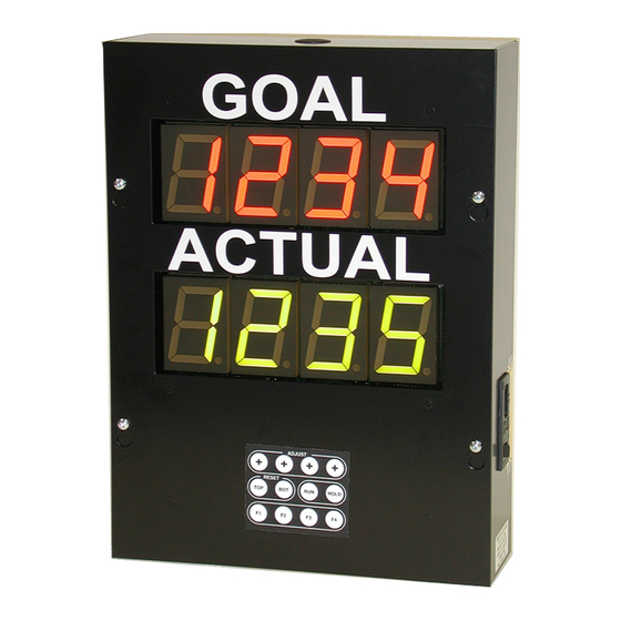
The Production Cycle Timer
2", 4 Digit, 2 Line, Goal / Actual Marquee with 4x3 Matrix Keypad
Firmware: PP-2110-543D
American LED-gible
®
Inc.
1776 Lone Eagle St.
Columbus, OH 43228
(614) 851-1100
Phone
(614) 851-1121
Fax
www.ledgible.com
www
ledgible@ledgible.com
e-mail
Model AF-2720-912
Owners Manual
Hardware: AB-2486-224D
Manual PB-2149-610
Revision F
April 6, 2016
Advertisement
Table of Contents

Summary of Contents for American LED-gible AF-2720-912
- Page 1 Model AF-2720-912 The Production Cycle Timer Owners Manual 2”, 4 Digit, 2 Line, Goal / Actual Marquee with 4x3 Matrix Keypad Firmware: PP-2110-543D Hardware: AB-2486-224D American LED-gible ® Inc. 1776 Lone Eagle St. Columbus, OH 43228 (614) 851-1100 Phone (614) 851-1121 www.ledgible.com...
-
Page 3: Table Of Contents
1.8 Proper use of the PCT Keypad..................16 2.0 Basic Operation........................17 2.1 Adjusting Register Values....................17 2.2 Basic Operation Example....................18 3.0 In Case of Difficulties......................19 3.1 Contacting American LED-gible® Inc................19 4.0 Product Specifications......................20 5.0 Limited Warranty........................21 6.0 ASCII Chart...........................22 7.0 Connection Labels........................24... -
Page 5: Getting Started
We will do everything we can to keep you happy with your purchase for many years to come. Please review this manual carefully, and if you have any questions, call, e-mail, or fax us and we will be glad to help you. American LED-gible support can be reached at: ®... -
Page 6: Unpacking The Unit
Every PCT is carefully tested, both mechanically and electrically, before shipment. Inspect the marquee for damage, which may have occurred in transit. If there is evidence of damage, file a claim with the shipper and notify American LED-gible. Save the shipping materials for inspection. -
Page 7: Introduction To The Pct Circuit Board
The Production Cycle Timer Owners Manual 1.4 Introduction to the PCT Circuit Board A convenient way to work on the PCT is to loosen the front panel, flip it over, and then temporarily support the font panel by hanging it on two of the box screws as shown in the picture below. Page 3... - Page 8 Customer connectors provide simple screw terminal termination for 22 to 16 gage wires for use by the customer. Factory connectors provide crimped pin termination for 20 gage wires. The primary purpose of the factory connectors is to provide American LED-gible with an alternate location to terminate factory installed wiring that will not consume customer screw terminals.
-
Page 9: 120Vac Power Connectors
The Production Cycle Timer Owners Manual 1.4.1 120VAC Power Connectors The PCT requires 120VAC at ½ Amp current draw to operate (without the optional stack light installed). However, If custom devices are connected to the silicon relay outputs, the maximum current draw could be as high as 1½ Amps. -
Page 10: Logic Input Connectors
The Cycle Timer Owners Manual 1.4.2 Logic Input Connectors The PCT has seven digital logic inputs. Each input is activated by connecting the input terminal to the GND terminal with a dry Optional Logic Input contact or an NPN (current sinking) output. Extension Cable Pinout If your PCT was purchased with the optional logic input extension cable, the factory will have already installed wiring... -
Page 11: Serial Port Connectors
The Production Cycle Timer Owners Manual 1.4.3 Serial Port Connectors The PCT has one serial communications channel that can be configured for RS-232 or RS-485 communications. Separate wiring terminals are provided for RS-232 and RS-485 wiring, on both the customer and the factory connectors. -
Page 12: Relay Output Connectors
The DC Sink relay outputs are reserved by ALI for future feature expansions to the PCT. Note: Do not connect any wiring to the 120VAC or DC Sink relay output connectors unless directed to do so by American Led-gible Inc. Factory DC Sink... -
Page 13: Status Indicator Lamps
The Production Cycle Timer Owners Manual 1.4.5 Status Indicator Lamps The PCT has several indicator lamps that are quite helpful for debugging wiring problems. To debug power wiring, apply 120VAC power to the PCT and then make sure the PWR indicator is illuminated. If it does not, then the 120VAC power wiring is probably incorrect. -
Page 14: Configuration Dip-Switches
The Cycle Timer Owners Manual 1.4.6 Configuration Dip-Switches The configuration dip switch blocks are used to configure semi-permanent PCT settings. These are settings that are likely to be decided upon when the PCT is first installed, and then never changed. PCT settings that are likely to change from week to week are set using the keypad on the front of the unit. -
Page 15: Selecting The Pct Timing Mode
The Production Cycle Timer Owners Manual 1.4.7 Selecting the PCT Timing Mode The PCT can be configured to time in tenths of seconds, seconds, tenths of minutes, minutes, tenths of hours, or hours. The timing mode is selected by three switches on SW2. Shown with switches 1, 7, and 8 ON SW2.8... -
Page 16: Selecting Time Minus Or Time Plus Stack Light Mode
The Cycle Timer Owners Manual 1.4.8 Selecting Time Minus or Time Plus Stack light Mode If you don't have the optional Red / Yellow stack light, this switch setting has no effect on your unit. By default, the factory sets switch SW2.5 to the OPEN or OFF position which selects Time Minus stack light mode. -
Page 17: 120Vac Power Installation
The Production Cycle Timer Owners Manual 1.5 120VAC Power Installation If your PCT was ordered with the optional American 120VAC line cord option, you will simply need to provide a standard 120VAC duplex near the PCT. However if your unit does not have the optional line cord, you will need to connect 120VAC power to screw terminals inside the PCT as shown below. -
Page 18: Logic Input Installation
The Cycle Timer Owners Manual 1.6 Logic Input Installation If your PCT was ordered with the optional count push button kit, or the optional photo-eye kit, some / all of the logic wiring you need may have already been completed by the factory. However you may still wish to review this section for information on how the PCT logic inputs are operated. - Page 19 The Production Cycle Timer Owners Manual If you are using a 12VDC photo-eye or proximity sensor, the PCT can supply up to ½ amp of power to the sensor. Be careful when connecting the +12VDC output to your sensor. If the sensor draws too much current, the fuse (F1) soldered to the PCT board will blow to protect the PCT power supply.
-
Page 20: Serial Communications Installation
The Cycle Timer Owners Manual 1.7 Serial Communications Installation As of May 12 2014, the PCT firmware (PP-2110-543B) does not make use the PCT serial port hardware. Future revisions of the PCT firmware may activate the serial port for use as a supervisor interface, or possibly to transmit data to slave displays, but at this time the serial port is not used. -
Page 21: Basic Operation
The Production Cycle Timer Owners Manual 2.0 Basic Operation Place the PCT front panel back on the box and apply power to the unit. When the PCT powers up, it first restores GOAL, ACTUAL, and other register values from backed up memory. If the PCT’s backed up memory has expired then all PCT registers are reset to default values. -
Page 22: Basic Operation Example
To set the RED TIME (RED) register, press the [F1] key three times to select the RED TIME (RED) register. Use the [+] keys to select a red time of 0005 minutes. Then press the [F4] key to apply the new RED TIME (RED) setting. American LED-gible ® Inc. -
Page 23: In Case Of Difficulties
PCT starts, if TJ1 is installed, additional startup code is executed. This code first performs a LAMP TEST, then the baud rate and address are displayed, and finally the PCT memory is erased which has the side effect of resetting all PCT registers to default values. 3.1 Contacting American LED-gible ® Inc. -
Page 24: Product Specifications
The Cycle Timer Owners Manual 4.0 Product Specifications GENERAL: Line Voltage 120VAC 60Hz or 50Hz Power Consumption ½ Amp typical, 1 ½ Amp Maximum Operating Temperature 0° F to 135° F (-17° C to +50° C) Operating Humidity 35% to 80% Dimensions 11”... -
Page 25: Limited Warranty
1776 LONE EAGLE STREET COLUMBUS, OHIO 43228 We will furnish you with shipping instructions. This warranty covers merchandise returned to American LED-gible ® (shipped prepaid) for repair, not in plant repairs. Should you need an in plant repair at your facility, American LED- gible will schedule a trip. -
Page 26: Ascii Chart
The Cycle Timer Owners Manual 6.0 ASCII Chart ASCII Hexadecimal Decimal ASCII Hexadecimal Decimal CHARACTER Code Code CHARACTER Code Code CTRL-A CTRL-B “ CTRL-C CTRL-D CTRL-E CTRL-F & CTRL-G CTRL-H CTRL-I CTRL-J CTRL-K CTRL-L CTRL-M CTRL-N CTRL-O CTRL-P CTRL-Q CTRL-R CTRL-S CTRL-T CTRL-U... - Page 27 The Production Cycle Timer Owners Manual ASCII Hexadecimal Decimal ASCII Hexadecimal Decimal CHARACTER Code Code CHARACTER Code Code DELETE Page 23...
-
Page 28: Connection Labels
The Cycle Timer Owners Manual 7.0 Connection Labels Example PC Wiring Connection to PC Example Logic Input Wiring DB9 RS-232 Port Illustrated Optional Customer Supplied Photo-Eye Shown Maximum Allowed Eye Power Draw is ½ Amp Page 24...
Need help?
Do you have a question about the AF-2720-912 and is the answer not in the manual?
Questions and answers