
Summary of Contents for Direct Voltage 5 Axis
- Page 1 Direct Voltage LLC 5 Axis Breakout Board Interface Adapter EMAIL:sales@directvoltage.com WEB: HTTP://directvoltage.com User Manual of 5Axis Breakout Board...
- Page 2 Direct Voltage LLC sales resources. Since Direct Voltage LLC basically provide OEM machine builders components to build their...
-
Page 3: Table Of Contents
Direct Voltage LLC 5 Axis Breakout Board Interface Adapter Contents Introduction and Features ......................1 Introduction ........................1 Features ......................... 1 Specifications ..........................1 Interfaces ........................... 2 Wiring Diagram for Reference ....................3 MACH3 Software Settings ....................... 3... -
Page 4: Introduction And Features
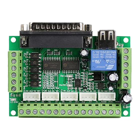
1 Introduction and Features 1.1 Introduction The latest upgraded 5 axis breakout board is specially designed for the CNC single axis 2-phase stepper driver controller, such as M542, M542H, MA860H, 2M542, 2M982, DM542(A), DM860(A) etc. single axis stepper driver controller series. With this 5 axis breakout board, any 1-5 single axis stepper driver controllers can be directly controlled by the PC via the MACH3, EMC2, KCAM4, etc. -
Page 5: Interfaces
Direct Voltage LLC 5 Axis Breakout Board Interface Adapter 3 Interfaces... -
Page 6: Wiring Diagram For Reference
Direct Voltage LLC 5 Axis Breakout Board Interface Adapter 4 Wiring Diagram for Reference 5 MACH3 Software Settings Note: The settings on MACH3 below is in condition that breakout board and stepper drivers are connected in common anode. 1. Check whether the MACH3 driver is installed correctly. - Page 7 Direct Voltage LLC 5 Axis Breakout Board Interface Adapter 2. Setup Units: Choose “MM’s” in Config->Set Default Units for Setup 3. Click “Config”->”Ports and Pins” on Main Interface.
- Page 8 Direct Voltage LLC 5 Axis Breakout Board Interface Adapter 4. Enter in “Port Setup and Axis Selection” to set “Port#1” and “Kernel Speed” shown as below. 5. Click “Motor Outputs” to set it shown as below. 6. Click “Iutput Signals” to set it shown as below.
- Page 9 Direct Voltage LLC 5 Axis Breakout Board Interface Adapter 7. Click “Output Signals” to set it shown as below.
- Page 10 Direct Voltage LLC 5 Axis Breakout Board Interface Adapter 8. Click “Spindle Setup” to set it shown as below.
- Page 11 Direct Voltage LLC 5 Axis Breakout Board Interface Adapter If you use PWM to control the spindle speed, you have to click “Pulley Selection” to set it shown as below. 9. Motor debugging. Click Config->Motor Turning and Setup...
- Page 12 Direct Voltage LLC 5 Axis Breakout Board Interface Adapter 10. Click “System HotKeys Setup”. Set X, Y, Z axis hotkey shown as below. Then you can manual control the corresponding axis motor turning via hotkeys.
Need help?
Do you have a question about the 5 Axis and is the answer not in the manual?
Questions and answers