Philips HDD084 Service Manual
Micro audio jukebox
Hide thumbs
Also See for HDD084:
- User manual (41 pages) ,
- Specifications (2 pages) ,
- Service manual (25 pages)
Advertisement
Quick Links
Download this manual
See also:
User Manual
Micro Audio Jukebox
Service Manual
TABLE OF CONTENTS
Technical Specification and Service hints......................1
Safety Instructions......................................................2
Instructions for Use.................................................... 3
Mechanical Instructions.............................................. 4
Exploded view and Service parts list............................. 5
Factory Service Mode testing....................................... 6
Overall Block diagram................................................. 7
Overall Electrical diagram........................................... 8
Component layout...................................................... 9
Revision list...............................................................10
©Copyright 2005 Philips Consumer Electronics B.V. Eindhoven, The Netherlands
All rights reserved. No part of this publication may by reproduced, stored in a
retrieval system or transmitted, in any form or by any means, electronics,
mechanical, photocopying, or otherwise without the prior permission of Philips
Version 1.7
HDD084/HDD085/HDD082/HDD086
All Versions
Chapter
3141 785 30487
Advertisement

Related Manuals for Philips HDD084


Summary of Contents for Philips HDD084
-
Page 1: Table Of Contents
All rights reserved. No part of this publication may by reproduced, stored in a retrieval system or transmitted, in any form or by any means, electronics, mechanical, photocopying, or otherwise without the prior permission of Philips 3141 785 30487 Version 1.7... -
Page 2: Technical Specification And Service Hints
Once the installation is completed, connect the GoGear to the power supply with the AC/DC Current consumption adapter. Launch the Device Manager at Start->Programs- >Philips GoGear HDD->Philips GoGear HDD on DC-IN SUPPLY (3.8V) your PC Battery Charging Current 370mA typ. - Page 3 USB cable. Make sure that Windows Media Player along with any other applications are closed. Launch the Philips Device Manager by double clicking the Device Manager icon at the task bar on your computer. The Philips Device Manager will detect the...
- Page 4 USB cable. Make sure that Windows Media Player along with any other applications are closed. Launch the Philips Device Manager by double clicking the Device Manager icon at the task bar on your computer. Select the REPAIR tab on the dialogue box and then click Repair to start repairing.
- Page 5 1.0 TECHNICAL SPECIFICATION and SERVICE HINTS Capture the log file from device Switch on the device in FSM mode by pressing and holding the Rec key and then the power key together. Device will switch on and FSM main menu will be displayed Scroll Down using the key to item 14 HDDinit...
- Page 6 DFUAPP.exe file from Symphony folder. Disconnect DFU USB cable from the device. Connect the device to the PC by normal USB cable and launch the Philips Device Manager to repair the device. (Download the latest version of the Device Manager application from Philips support website http://www.philips.com/support)
- Page 7 1.0 TECHNICAL SPECIFICATION and SERVICE HINTS For HDD086/HDD085/HDD082 (MTP mode device) Disconnect DFU USB cable from the device. Unzip the Factory.rar file to your PC. You should find three folder name “Bootloader”, Open the device, displace will show “BOOT “DM” & “Drive_I”. LOADER APPLICATION Version 4.0”.
- Page 8 1.0 TECHNICAL SPECIFICATION and SERVICE HINTS seconds and then start up as usual. MTP mode installation procedure after replaced the mainboard Note: Applicable for HDD085/HDD082 only Repeat the recovery procedure for flash corrupt problem from step 9 to 16. 14. Connect the device with PC by normal USB cable again for MTP connection.
- Page 9 2.0 SAFTETY INSTRUCTIONS WAARSCHUWING WARNING Alle IC’s en vele andere halfgeleiders zijn All ICs and many other semi-conductors are gevoelig voor electrostatische ontladingen susceptible to electrostatic discharges (ESD). (ESD). Careless handling during repair can reduce life Onzorgvuldig behandelen tijdens reparatie kan drastically.
-
Page 10: Instructions For Use
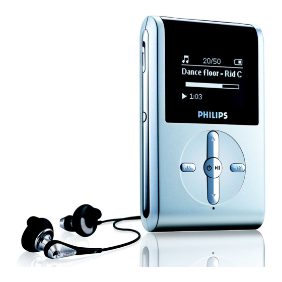
3.0 Instructions for use Overview of controls and connections USB cable connector Headphones jack 5V DC Charging socket HOLD slider To disable key press LCD display Dynamically displays menu, options and track information VIEW To switch between root menu, library and now playing screens Scroll;... -
Page 11: Mechanical Instructions
4.0 MECHANICAL INTRUCTIONS Set Disassembly 1. Remove the Cosmetic screw with an Allen key 2. Use a screwdriver to carefully lift up the back cover of the device. 3. Gently open up the back cover. 4. Remove 4 x screws. See arrows... - Page 12 4.0 MECHANICAL INTRUCTIONS 5. Open up and remove the bottom part. 6. Remove the battery pack and then the hard disk 7. Take out the 2 screws on the PCB assembly to replace it from the casing. Overview of the disassembly parts Hard Disk Mainboard /...
-
Page 13: Exploded View And Service Parts List
5.0 EXPLODED VIEW & SERVICE PARTS LIST MECHANICAL PARTS 314017750142 FRONT CAB. ASSY HDD084 SILVER 314017750591 COVER-REAR LAQ ASSY HDD084 SIL 314017750132 REAR CABINET ASSY HDD084 314017870131 BATTERY PACK 610MAH LI POLYMER 314017900191 PCBA KIT ASSY HDD084/00/05 314017900231 PCBA KIT ASSY HDD085/00/05... -
Page 14: Factory Service Mode Testing
6.0 FACTORY SERVICE MODE TESTING Device Key Test Programming the device using for stand-alone FSM LCD Backlight Test 5-key Remote Key Test SDRAM Read/Write Test The following is the description for programming the device in stand-alone LCD and Back Device Keypad SDRAM Self-refresh Test Light Test Test... - Page 15 6.0 FACTORY SERVICE MODE TESTING Test USAGE Description 1. FSM 2. LCD Test Power ON screen 3. Device Keypad Test 4. 5-key Remote Key 5. SDRAM Read/Write 6. HDD Test 7. Audio Test 8. FM Tuner <HDD 084> 9. Battery Level <FSM/DVT X.X>...
- Page 16 6.0 FACTORY SERVICE MODE TESTING • The Test patterns which will be displayed will be as shown LCD pattern 1: White screen LCD pattern 3: Checkerboard pattern LCD pattern 2: Black screen with a white square at right upper corner LCD pattern 4: Black background...
- Page 17 NOTE: The LCD patterns will changed after the new test patterns are • Press RIGHT to enter the test. “Remote Key Test” is displayed on the received because the LCD that will be used with HDD084 is black and LCD. white LCD and cannot display greyscale.
- Page 18 <SDRAM Self refresh FAIL > > a specific location and read back the data to verify the data Integrity. < > < > <HDD084 SDRAM R/W Test > <HDD084 SDRAM R/W Test > < > < > <SDRAM Under Test <SDRAM R/W OK...
- Page 19 After connecting it to the PC. mentioned in 4.1.14. • • Create a file “HDD084.txt”. Press LEFT to exit the test, tuner will be disabled and the test browse • screen will be entered where a next test can be selected.
- Page 20 LCD for 10 seconds and the device goes to NON-USB CHARGING MODE shutdown mode (TBD). • Press LEFT key to exit the test. • Note this test should be done without initialising the HDD. <HDD084 BATTERY CHARGING TEST> < X.XXXV YYY.YmA > <CHG.STATUS > < Adaptor STATUS >...
- Page 21 The recoded file can be verified in “AUDIO TEST CASE” (4.1.9) • Press LEFT to exit the test. • The battery level will be refreshed regularly every 1 second. MIC Recording Test Steps <HDD084 FM RECORDING > • Connect a microphone. < F106.50 > • <STEREO >...
- Page 22 6.0 FACTORY SERVICE MODE TESTING Steps Powering Off <HDD084 EXTERNAL RTC > <HDD084 EXTERNAL RTC > • Pressing play key for longer than 2 seconds causes system power off. < > < > • Release the PLAY key once “OFF” is displayed in the LCD. Note that <RTC under Test...
- Page 23 6.0 FACTORY SERVICE MODE TESTING HDD initialisation Steps • Select the test and press right key to enter the test • Initialize the HDD...
-
Page 24: Overall Block Diagram
GPIO Reset Reset logic 12MHz 32KHz Headphone LCD Interface Line In Line Out sysclock RTCclock interface amplifier LCD Connector LEGEND BOARD COMPONENTS FM_ANT EEPROM FM tuner M24C08 CONNECTORS LCD_BL_CTRL EXTERNAL DEVICES Headphone 96x64 connector HDD084 Only, not for PSA610 RTC_OUT... - Page 25 100n 100R TIMER 2471 100n MMBZ15VALT1 2472 100n 2473 100n 2474 100n SETNAME CLASS_NO 2005-04-12 3PC330 PBAS HDD084 2005-03-24 3140 178 0012 2005-03-07 HDD084 2004-12-10 2004-12-10 2005-04-12 2004-09-23 NAME RAYMOND CHOI SUPERS. CHECK DATE 2004-06-11 KONINKLIJKE PHILIPS ELECTRONICS N.V. 2004...
- Page 26 Φ GPIO SUPPLY V3V3_D GPIO-C VDDSHV GPIO-E F493 GPIO-7 GPIO-8 VDDSHVREG TEST SETNAME 2005-04-12 CLASS_NO PBAS HDD084 3PC330 2005-03-24 3140 178 0012 2005-03-07 HDD084 2004-12-10 2004-12-10 2005-04-12 2004-09-23 NAME RAYMOND CHOI SUPERS. CHECK DATE 2004-06-11 KONINKLIJKE PHILIPS ELECTRONICS N.V. 2004...
-
Page 27: Component Layout
9.0 COMPONENT LAYOUT... - Page 28 9.0 COMPONENT LAYOUT...
- Page 29 9.0 COMPONENT LAYOUT...
-
Page 30: Revision List
• Include content on HDD082/17 • Chapter 5 Changes in the service 12NC on the following parts FRONT CAB. ASSY HDD084 SILVER (314017750142) COVER-REAR LAQ ASSY HDD084 SIL (314017750172) REAR CABINET ASSY HDD084 (314017750132) • Chapter 5 Adding of the following new service parts HDD 1"... - Page 31 10.0 REVISION LIST Version 1.6 (3141 785 30486) • Chapter 1 Added recovery procedure for flash corrupt problem for HDD084/HDD085/HDD02 and MTP mode installation procedure after replaced the mainboard for HDD085/HDD082. • Chapter 5 Added new service 12NC on the following part DFU CABLE (824041001931) Version 1.7 (3141 785 30487)
Need help?
Do you have a question about the HDD084 and is the answer not in the manual?
Questions and answers