
Summary of Contents for GS Instruments Protek 7830
- Page 1 Protek 7830 Manual Get Pricing & Availability at ApexWaves.com Call Today: 1-800-915-6216 Email: sales@apexwaves.com https://www.apexwaves.com/analyzers/protek/protek-analyzers/7830...
- Page 2 USER’S MANUAL...
- Page 3 Update Spec. 3/2009 Version 2.2 Update Spec In order to keep the Protek 7830 Spectrum Analyzer continuously updated, information in this manual is subject to change without notice. Please contact us, if you have any questions about version upgrade and amendment.
-
Page 4: Safety Symbols
Safety Symbols Danger symbol identifies conditions or practices that could result in injury or loss of life Caution symbol identifies conditions or practices that could result in damage or fire. Ground symbol identifies conditions or practices that need grounding. - Page 5 Safety Instruction No Unauthorized Disassembling Do not remove the instrument cover. Only GS Instruments’ Service technicians are Instruments that appear damaged or defective allowed to repair the instrument. should be secured against unintended operations until they are repaired by qualified service technicians. Also, unauthorized disassembling makes the warranty void.
- Page 6 Battery Protek 7830 Ni-MH battery is rechargeable. Battery is recharged based on the battery temperature. Charging is controlled from the power of the battery cell and the temperature of the battery. The Ni-MH Rechargeable battery is going to increase temperature slowly until the temperature is extremely higher.
- Page 7 Operating personnel must use Ni-MH Rechargeable Battery and do not operate near explosives The battery usage time can change due to the using period, environment and temperature. As time goes by, the battery-running time will decrease and eventually need to replace. Operating personnel should phase in a new battery when the battery-running time is less than half hour (The warranty period is 6 month, after instrument use has begun.) Operating personnel should not use this instrument and/or keep the battery in place for...
- Page 8 ◎ Buyer operates instrument against the environmental specifications for this instrument. With the exception of the above articles, GS Instruments product is warranted for an initial purchaser. If this instrument is resold to the other end-users, warranty is not transferred.
- Page 9 Accessories Carrying case AC Adaptor Carrying Strap RS-232 Cable Coaxial Cable N-BNC Power Cable Earphones Adaptor Ni-MH (Rechargeable User’s Manual GUI Software CD Antenna Battery) 6PCS X 2PCS ※ Standard Option...
-
Page 10: Table Of Contents
Table of contents 1. Introduction Overview……………………………….……………………………..……………….11 2. Features Main Features …………………………………………………………………….…12 3. Functions Spectrum Analyzer……………………………………………………………..…….13 Frequency Counter……………………………………………………….………….13 Specifications………………………………………………………………...……….14 4. Instrument overview Front Panel………………………………………………………………………...….18 Rear Panel…………………………………………………………………………….20 Side Panel…………………………………………………………………………….21 Top Panel…………………………………………………………………………..….22 5. Basic operation Before Power On…………………………………………………………….……….23 Power On……………………………………………………………………………...24 Turn on Power of Instrument………………………………..…………………….25 Description of operation screen…………………………..……………………….26 Reception Mode……………………………………………………………..……….32 Sweep Mode………………………………………………………………………….33... - Page 11 Frequency Counter…………………………………………………………….…….60 Power Source………………………………………………………………..……….62 Level Unit………………………………………………………………………..…….63 Reset………………………………………………………………………………..…64 Baud Rate…………………………………………………………………………..…65 Connection for PC……………………………………………………………………66 Auto Power……………………………………………………………………………67 Offset…………………………………………………………………………..………68 Menu……………………………………………………………..…………………….69 System……………………………………………………………..…….……………73 6. Description of key operating Run [GHz] …………………………………………………………………….………76 Mode [MHz] ………………………………………………………………..…………76 Sweep [kHz] …………………………………………………………….……………77 Marker [DEL] …………………………………………………………………………77 No. 1 [Start/Stop] …………………………………………………….………………78 No. 2 [Span] ………………………………………………………………..…………78 No.
-
Page 12: Introduction
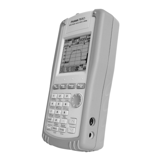
Introduction Overview The Protek 7830 is a handheld spectrum analyzer and it is optimized to analyze signals for the radio frequency equipment. The Protek 7830 has adopted a synthesizer method and has a wideband reception range of 100 kHz to 2,900 MHz. The characteristics of frequency response of the... -
Page 13: Features
Features Main Features 100 kHz to 2,900 MHz measurement range Frequency Spectrum Analyzing Function and Frequency Counter Function Measures and demodulates N-FM, W-FM, AM, SSB signals Built-in Frequency Counter Accurate Signal Level Measurement Marker/delta Marker/Squelch Adjustment Function ... -
Page 14: Functions
Functions Spectrum Analyzer Spectrum: Peak Search, Marker to Center, Channel Power Function Internal Attn.: The input range can be extended by internal Max 35 dB Attn. function. Sweep Mode: Single Run, Free Run, Squelch Run Selectable Squelch Function: The Squelch Level may be adjusted to any ... -
Page 15: Specifications
Specifications Frequency Range Frequency 100 kHz to 2,900 MHz Resolution Min. 6.25 kHz Accuracy TXO : ± 3 PPM / Display : ± 1.5 PPM Wide FM : Approx. 180 kHz @-6 dB W-FM / N-FM Narrow FM : Approx. 12.5 kHz @-6 dB / AM / SSB AM/SSB : Approx. - Page 16 Specifications asdf Speed Min. 500 msec Sweep Trigger Source Narrow FM / Wide FM / AM / SSB Free Run / Single Run / Continuous Wave Trigger Mode / Squelch Run Trigger Level TTL Level Maker / Delta Maker / Peak Search / Marker Mode Marker to Center / Channel Power Trace &...
- Page 17 SMPS Type AC Adapter (DC 12 V Output) Adapter Car-Adapter (DC 12 V Output) Off/ 5 min./ 10 min./ 20 min./30 min. Auto Power On/Off The Protek 7830 can be quickly recharged using a Ni-MH rechargeable battery. safe usage, strongly...
- Page 18 Specifications Physical 4.4 ”(W)×10 ”(H)×2.3 ”(D) Dimension Specifications Approx. 0.70 Kg(1.54 lbm) Weight (including Antenna, except Battery) Standard Antenna (Receive Only), SMPS Type AC Adapter, Fuji-AA type NI-MH Accessories Rechargeable Battery (6 PCS, 1.2 V 2,700 mAh), Manual, Coaxial Cable, Earphones, Carrying Case, Carrying Belt, RS-232C Cable, Adapter (N-BNC), Software for PC Application Optional Matching Pad (75 Ohms to 50 Ohms), F-BNC Adapter, Car Adapter,...
-
Page 19: Instrument Overview
Instrument overview Front Panel Front Figure Mode Sweep Marker Shift Power Menu Enter The LCD screen can display the signal input level, frequency and amplitude values, and system data Power Key Key Pad Key to turn ON/OFF of the system ... - Page 20 Front Panel Mode Key to set up the Reception Mode or input the MHz unit for frequency value input Sweep Key to set up the Sweep Mode or input the kHz unit for frequency value input Marker Key to select the Marker Function: Marker, Delta Marker, Squelch Marker, Peak Search, Marker to Center, and Channel Power...
-
Page 21: Rear Panel
Rear Panel Rear Figure Belt Clip Users can yoke the Protek 7830 on a belt. Speaker Users can use the speaker to output the modulated audio from RF signal level. Reset Key Users can use this Reset key from system’s malfunction or memory reset. -
Page 22: Side Panel
Side Panel Side Figure DC Input Jack Users can use this DC input jack for power supply and battery charging with SMPS type AC/DC Adapter or Car Adapter. RS-232C Connector (8 pin mini DIN connector) Users can use the RS-232C connector for PC communications with a serial cable. -
Page 23: Top Panel
Top Panel Top Figure Input Connector for Signal Level Users can connect the antenna or coaxial cable to this connector on the system. The maximum input voltage is 5 Vrms. Input Connector for Frequency Counter Users can connect the signal source to this connector as an input. The maximum input voltage is 5 Vrms. -
Page 24: Basic Operation
Basic Operations Before Power ON For the insertion of batteries, please release the screw on the battery cover on the bottom of the instrument. And put AA Type Ni-MH rechargeable batteries (Total 6 PCS) in. To charge the batteries after inserting batteries, connect the DC cable plug of SMPS type adaptor to DC jack of the system (DC output: 12V). -
Page 25: Power On
Power ON To turn on the system power, Press the key. When the system power is ON, the last displayed screen from the previous usage will be displayed (Previous setup status). This system supports shortcuts with the combination of keys. To use this shortcut function, press the key and press the numerical key. -
Page 26: Turn On Power Of Instrument
Turn on power of instrument STEP 1 Power On - Push the Key. STEP 2 ( Adjust to LCD Contrast) - Push the Key. - Push the LCD CONTRAST (No.8) Key. - Adjust to desired LCD Contrast using the Up/Down Keys or Knob Key. -
Page 27: Description Of Operation Screen
Description of operating screen 1. ICON window 2. Frequency Input window 3. Wavy pattern window 4. Squelch window 5. Marker window 1. ICON window ⓐ ⓑ ⓒ ⓓ ⓔ ⓕ ⓖ... - Page 28 Description of operating screen ⓐ Shift State Indication Normal state Pushing the shift key changes the icon. Shift Input state ⓑ Reception Mode State Indication Wide Frequency Demodulation Mode Narrow Frequency Demodulation Mode Amplitude Modulation Mode Single side band Demodulation Mode Pushing the mode key changes the icon.
- Page 29 Description of operating screen ⓕ Buzzer On/off Indication Buzzer Off Icons are changed by Dot(Buzzer) key Buzzer On ⓖ Battery Residual Indication Full Empty 2. Frequency Input window ⓔ ⓐ 주파수 값 표시 ⓒ ⓓ ⓑ LEVEL ATTN...
- Page 30 Description of operating screen ⓐ Center Frequency Indication NONE Maker 1 Frequency Indication Maker 2 Frequency Indication Frequency Counter Value Indication CHPW Channel Power Value Indication Indication of Frequency Value of each Mode ⓑ Level Value Indication Indication of Level Value of each Mode. ⓒ...
- Page 31 Description of operating screen 3. Wavy pattern ⓒ window ⓐ ⓑ Indication Reference Indication to Vertical Level Value of ⓐ Value Screen Wavy pattern window. Level Value [Please refer screen level establishment in basic operations Resolution of Screen ⓑ for further details] Level Value Marker Indication Center...
- Page 32 Description of operating screen 4. Marker Window Center Marker, Marker 1, When Squelch Marker ⓐ Center Frequency CENT SPAN Span Frequency Step Frequency STEP When Delta Marker ⓑ MKR1 Marker 1 Frequency LEV1 Marker 2 Level Value Marker1- Marker2 Level Value DIFF When Measuring Channel Power ⓒ...
-
Page 33: Reception Mode
Reception Mode Reception Mode has total (4) four modes for demodulation when receiving. Wide Frequency Modulation Wide-FM Wide FM RBW (Resolution Bandwidth) 180 kHz Narrow Frequency Modulation Narrow-FM Narrow RBW (Resolution Bandwidth) 12.5 kHz Amplitude Modulation SSB /AM RBW (Resolution Bandwidth) 2.4 kHz Single Side Band Modulation SSB /AM RBW (Resolution Bandwidth) 2.4 kHz The Wide FM mode is ordinary used to interpret a large signal of... -
Page 34: Sweep Mode
Sweep Mode The Sweep mode is used to interpret the characteristics of input signals. Every each characteristics of the sweep mode is as follow. Analyzing execution consecutively Free Run Only 1 time Execution Single Run Run by higher than Squelch level Squelch Run (Similar Trigger Mode of Oscilloscope) Establish this mode by pushing the Sweep (kHz) -
Page 35: Set Up Span
Set up Span Setting of step for Span means Frequency Resolution and Span can be adjusted from 1MHz to 400MHz. And the step at Narrow FM, SSB and AM can be set 1MHz to 2MHz. Wide FM from 1MHz to 20MHz is 1MHz step and step at 20MHz to 400MHz can be set at 20MHz step. -
Page 36: Frequency Input
Frequency Input Chosen Reception Mode, Sweep Mode and Span are showed on the top center of LCD. At first, choose Reception Mode and Sweep Mode to get a sense of the Frequency Bandwidth and a specific feel for analyzing. Choosing Frequency Value is a way to inputting Center and Start/Stop Frequency. - Page 37 Frequency Input STEP 1 - Check the state of Frequency Input Window. You can input Center Frequency when state of Frequency Input Window is CENT STEP 2 - Input a desired Center Frequency STEP 3 - Input a unit by using the Run , Mode and Sweep STEP 1...
-
Page 38: Adjust Screen Level
Adjust screen Level To Settle Top Level- Reference Level and Level Resolution on screen. “RLEV” is an abbreviation of Reference Level. Choose through the Up/Down Keys and establish the level using the Enter Key. Top Level in the vertical axis would be changed to be established Value. -
Page 39: Run-Scanning
Run-Scanning Run-Scanning is a process interpreting Frequency according to established Frequency Bandwidth and Span. And Run- scanning processes operates by established Sweep Modes... -
Page 40: Marker
Marker Protek 7830 has Center Marker, Marker 1, Delta Marker (Marker1 and Marker2) and Squelch Marker. Each Marker Mode is displayed on the top- left as a Marker Mode ICON. Marker Mode Marker ICON Remarks ICON Center Marker Center Marker... - Page 41 Marker Center Marker Center Marker is not a Mode the users can select when using Mark Mode in the basic operations. When inputting Start Frequency and Stop Frequency, Center Frequency, the information will appear automatically. Frequency and Level on Center Frequency will be indicated on Frequency Input Window.
- Page 42 Marker Marker 1 To use Marker 1 , press the Marker (DEL) key in Center Marker status. When it turns to Marker 1 mode, Marker mode icon is changed to . And frequency input window is changed to Center Marker to Marker 1 To move the Marker 1, use the Up/Down keys, or the Knob key.
- Page 43 Marker Delta Marker Press the Marker (DEL) Key until the Marker mode icon is changed to Delta Marker in the display window. And in this case, Marker 2 is added. The Marker mode is the total four modes. And the changing order of Marker mode is as below: Center ...
- Page 44 Marker STEP 1 - Press the Marker (DEL) Key. - Check the Delta Marker mode in the display window STEP 2 - To move the Marker 1 to the desired plot point, please use the Up/Down keys, or Knob key. - Then, the frequency value and level value of Marker 2 are displayed in the frequency input window.
- Page 45 Marker Squelch Marker To know the magnitude of frequency, users can use the Squelch Marker. Also, users can set up the Squelch Marker for setting the Squelch Level of Sweep mode and speaker output for a larger signal than Squelch Level through modulation for audio frequency ranges.
- Page 46 Marker STEP 1 - Press the Marker key. - Check the Squelch Marker mode. STEP 2 - Move the Squelch Marker to the desired point using the Up/Down Keys or Knob Key. - The squelch value is displayed in the lower right display window.
- Page 47 Marker Peak Search Functions using Marker To use the Peak Search function, this function must be run in Marker 1 mode. Press the Marker (DEL) Key until the Marker 1 icon Marker 1 are displayed in the display window. The Marker mode is the total four modes and the changing order of Marker mode is as below: Center ...
- Page 48 Marker STEP 1 - Press the Marker (DEL) Key. - Check the Marker 1 mode in the display window. STEP 2 - Press the Shift STEP 3 - Press the No. 4 (PK Search) key. Then, the Marker 1 is moved to the peak point, and the frequency value and level value are displayed in the frequency input window The function for Peak Search must be run in only Marker 1 mode...
- Page 49 Marker Peak/Marker to Center To use the function of moving Marker 1 to the center or Marker 1 to the peak value of the display window, this function must be run in Marker 1 mode. Press the Shift key to change the upper right icon to .
- Page 50 Marker STEP 1 - Press the Marker (DEL) Key. - Check the Marker 1 mode in the display window. STEP 2 - Move the Marker 1 to the desired point using the Up/Down Keys or Knob STEP 3 - Run the function for Peak Search by pushing Shift + No.4 - Make sure that the marker is located on the peak signal.
- Page 51 Marker Channel Power Measurement To run the function for channel power measurement, users can get into this mode by pushing Shift + No. 6 (CH Power) or selecting Channel Power item in the main menu. The above display shows the illustration of the channel power measurements.
- Page 52 Marker STEP 1 - Press the Shift + No. 6 (CH Power) Or - Select CH. POWER item on Marker in the main menu. STEP 2 - Input the center frequency. STEP 3 - Move the Marker to select the desired channel power ranges using the Up/Down Keys or Knob STEP 4...
-
Page 53: Setting Of Attenuator
Setting of Attenuator The internal attenuator is used for maximum input signal -20dBm with Setting for Menu function. Internal or External To set the internal attenuator, press the Shift key to change the Attenuator upper right icon And press the No. 9 (ATTN) key. -
Page 54: Lcd Light
LCD Light The LCD Light is designed to ease the use of the instrument in a dark location. Press the Shift key to change the upper right icon And press the No. 7 (LCD Light) key. *The Power ON/OFF of the LCD Light will toggle STEP 1 - Press the Shift STEP 2... -
Page 55: Lcd Contrast
LCD Contrast The function of LCD contrast is to adjust the contrast for the remaining battery capacity. Press the Shift key to change the upper right icon And press the No. 8 (LCD Contrast) key. The LCD contrast is adjusted by using the Up/Down keys or Knob key. -
Page 56: Buzzer On/Off
Buzzer ON/OFF User can set the Buzzer ON/OFF (Toggle ON/OFF) Press the Shift Key. Then the Icon of left upper window is changed to shift icon And press the Dot Key. STEP 1 - Press the Shift STEP 2 - Press the Dot... -
Page 57: Save/Load
Save/Load The function of Save/Load is for the Waveform and Setup Status. The function of Save is for concurrently saving the Waveform and Setup Status in memory. And the saved Setup Status in memory includes the following information: Reception mode, Sweep mode, Frequency range, Step value, and Span value. - Page 58 Save/Load STEP 1 - Press the Shift STEP 2 - Press the Enter STEP 3 - To save the waveform or setup status, a name with at least 7 characters is required. - To select each character, use the Up/Down keys.
- Page 59 Save/Load Load STEP 1 - Press the Shift STEP 2 - Press the Menu key STEP 3 - To load the waveform or setup status, select a filename to retrieve. - To select the first character. Use the Up/Down keys. And press the Enter The function of Load is to load the saved waveform and setup status.
- Page 60 Save/Load Delete STEP 1 - Press the Menu STEP 2 - To select the DELETE, use the Up/Down keys or Knob key and press the Enter STEP 3 - To delete the saved data, select the user’s saved data using the Up/Down keys or Knob key.
-
Page 61: Frequency Counter
Frequency Counter Select the F.counter under Main Menu – function The input connector for the frequency counter is BNC connector. When the input level is inputted into the Frequency Counter, the measured frequency value is displayed in the frequency input window Input level is as below. - Page 62 Frequency Counter STEP 1 - Press the Menu STEP 2 - To select the FUCTION, use the Up/Down keys or Knob key and press the Enter key. - Then sub menu is opened. STEP 3 - To select the F. COUNTER (Frequency Counter), use the Up/Down keys or Knob key and press the Enter STEP 4...
-
Page 63: Power Source
Power Source To check the battery’s remained capacity Battery, users can refer to the Checking battery icon on the upper area of the display window for Battery How to use and replace the battery [Please refer to the batter section in details.]... -
Page 64: Level Unit
Level Unit The setting for level unit can be set up in the Menu. Setting of The level unit can be set up as below the Unit □ dBm □ dBuV □ dBmV STEP 1 - Press the Menu STEP 2 - To select the LEVEL UNIT, use the Up/Down keys or Knob key and press the Enter... -
Page 65: Reset
Reset The function of Reset is for initializing the memory or system. The three kinds of resets are supported. And these resets are run through the Menu Preset System Reboot for initial setup status. (Center Frequency, Span Frequency, Marker and etc) Memory CLR ... -
Page 66: Baud Rate
Baud Rate The setting of the baud rate is for the transmission speed. Setting of The Baud Rate between PC and 7830 system is as below. the Baud Rate 115,200 BPS 57,600 BPS 38,400 BPS 19,200 BPS 9,600 BPS 4,800 BPS STEP 1 - Press the Menu STEP 2... -
Page 67: Connection For Pc
Connection for PC To connect 7830 to a PC, carefully follow the procedures as below. Setting of Make sure the serial cable is connected from a PC to 7830. Connection Choose “CONNECT PC” on the main menu. for PC Run 7830 GUI Program on the PC. STEP 1 - Press the Menu STEP 2... -
Page 68: Auto Power
Auto Power Saving The Auto Power saving function is used to conserve system power. When “NONE” is not selected, the power source will be turned off automatically based on the time users select. The auto power OFF time is same as below NONE 05MINUTES 10MINUTES... -
Page 69: Offset
Offset Level Offset compensates for any loss due to the cabling. Offset adds the value of +Offset to all the values of measurement. STEP 1 - Press the Menu key twice. STEP 2 - Set the cursor on Offset using the Up/Down Keys or knob Key. -
Page 70: Menu
Menu Functions in the main menu can be selected using the combination keys or through the Menu. The functions that can be selected in the main menu mode are as below. Level Unit Reset Band Rate Connect PC To exit from Menu or System, push the Menu Key or push the Dot key. - Page 71 Menu STEP 1 - Press the Menu STEP 2 - To select functions users want, use the Up/Down Keys or the Knob Key. STEP 3 - Push the Enter STEP 4 - After selecting function of sub items or On/Off, push the Enter STEP 5 - Exit the Menu after pushing the Menu Key twice.
- Page 72 Menu Spectrum Set up the functions of Function Spectrum and frequency Frequency Counter counter. TEST Mode N-FM Reception Mode. W-FM Reception Mode Free Run Set up the Sweep Mode. Sweep Squelch Run The mode can be set up Mode with the Shift Key.
- Page 73 Menu Restarting the System and Pre Reset clear all the parameters for set Memory CLR Reset Delete the stored data All Reset – restarting the System INI system and delete the stored data 115,200 BPS 57,600 BPS Select the speed of serial 38,400 BPS Band Rate communication between the...
-
Page 74: System
System There are modes that select the function using the Shift Key and the other keys. Also, the functions can be selected from main Menu and System Menu.. To exit from Menu or System, push the Key or push the Dot key, this will move users up to higher menu items in the tree structured menu. - Page 75 System Get into System Menu STEP 1 - Press the Menu - Or Shift + No. 0 key is a shortcut for the System Menu (Go to Step3) STEP 2 - Press the Menu Key once more. STEP 3 - To select desired function, use the Up/Down Keys or the Knob STEP 4...
- Page 76 System None 05 Minutes Select auto power saving Auto Power 10 Minutes mode. 20 Minutes 30 Minutes Select Buzzer On/Off. Buzzer LCD Light Select LCD Light On/Off. LCD Contrast 1 to 10 Step 0 dB 10 dB 20 dB INT. Atten. 30 dB 35 dB Offset...
-
Page 77: Run [Ghz]
Description of key operations Run [GHz] Instruction to start scanning frequencies After power on, this button will work as it did under the most recent setup, or when Squelch Run or Single Run function is activated. [Please refer to the Scan section for basic operations in details if needed] Selecting a unit (GHz) to input Start/ Stop/ Scan/ Center ... -
Page 78: Sweep [Khz]
Sweep [kHz] Selecting Sweep Mode This button selects the Sweep Mode such as FREE Run SQUELCH Run and SINGLE Run [Please refer to the Sweep Mode section for detailed basic operations.] Selecting a unit (kHz) to input Start/ Stop/ Scan/ Center ... -
Page 79: No. 1 [Start/Stop]
No. 1 [Start/Stop] Press the No. 1 key to input the value of 1. To input the value of numeral 1 in the Start/Stop/Scan/Center frequencies, please use the No. 1 Key. Pressing the Shift Key and No.1 key will activate the ... -
Page 80: No. 3 [Level]
No. 3 [Level] Push the No. 3 key to input the value of 3. In order to input the value of numeral 3 in the Start/Stop/Scan/Center frequencies, push the No. 3 Key. Display Level Adjustment Function by pushing Shift ... -
Page 81: No. 5 [Mkr To Cnt; Marker To Center]
No. 5 [MKR to CNT; Marker to Center] Push the No. 5 key to input the value of 5 Push the No. 5 Key to input the value of numeral 5 in the Start/ Stop /Scan/ Center frequencies. Activate the Marker to Center Function using the Marker menu after ... -
Page 82: No. 7 [Lcd Light]
No. 7 [LCD Light] Push the No. 7 key to input the value of 7. When inputting the value of numeral 7 in the Start/Stop/Scan/Center frequencies, the No. 7 Key is used LCD Light Function after pushing the Shift ... -
Page 83: No. 9 [Attenuator]
No. 9 [Attenuator] Push the No. 9 key to input the value of 9. To input the value of numeral 9 in the Start/Stop/Scan/Center frequencies, the No. 9 Key is used Attenuator Setup Function after pushing the Shift By pushing the Shift key and then pushing the No. -
Page 84: Shift
Shift Using the Function Key The Shift Key does not perform any functions by itself. The Shift Key is used to perform functions printed below the numeral keys. If the shift key is pressed twice, CENT/SPAN located on the bottom of display is changed to START/STOP. -
Page 85: Menu [Load]
Menu [Load] Menu Function Various functions can be selected after entering Menu.. At the Menu, pushing the Menu Key again; it will activate the System Menu. [Refer the section of Menu and System of basic operation if need more detail] Load Function after pushing the Shift Key. -
Page 86: Up/Down Keys And Knob Key
Up/Down Keys and Knob Key Up/Down Keys and Knob Key Functions Up/Down keys and knob are used for the movement of markers and menu / system items... - Page 88 1. Protek G632 1. PROTEK G632 Protek G632 has been developed as a CW Signal Generator, which generates signal at -55 to - 65dBm within 30MHz to 2.9GHz bandwidth. G632 is connected to Protek7830 via RS-232 2. Features Protek G632 is a tracking generator for handheld Spectrum Analyzer 7830.G632 supports signal generating function &...
- Page 89 User’s Manual 4. Operation PROTEK 7830 – MENU – MENU - GEN OUTPUT – “LEVEL SELECTION” (-55/-60/-65dBm) (Operation) (Signal Generation) 5. G632~7830 Level Setting Procedure 1) Connect cable between G632 and 7830 2) Signal generated from G632 at -60dBm 3) Check 7830 Level 4) Level difference between -60dBm and 7830 can be compensated from “offset”...
- Page 90 6. Application: 900MHz Band Pass Filter Test <Test Conditions> A. Tracking Generator Output Signal Level: -60dBm B. Measuring Device: 900MHz Band Pass Filter C. Test Block Diagram RS 232 Cable <Test Results> A. 7830 Output Signal Level: -61.70dBm B. Path Loss(G632~7830): 1.5dB 1) Band Pass Filter: 1.4dB 2) Cable Loss: 0.1dB C.
- Page 91 User’s Manual 7. Cautions when linking G632 to 7830 A. Fix Int. Atten.: Fix INT. Atten of 7830 to 20 dB when connecting with G632. B. Ext. Atten. - Ext.Atten of 7830 disabled when connecting with G632. C. 7830 Mode Change: Changing Mode disabled when connecting with G632.
Need help?
Do you have a question about the Protek 7830 and is the answer not in the manual?
Questions and answers