Table of Contents
Advertisement
Advertisement
Table of Contents

Subscribe to Our Youtube Channel
Summary of Contents for Dorma MUXD 19
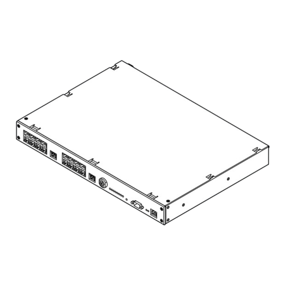
- Page 1 Installation Manual DORMA MUXD 19" (B6L 19'')
-
Page 3: Table Of Contents
B6L 19" technical Data ..... . 25 MUXD 19" technical Data ..... 26... -
Page 4: General Information
Despite every effort to prevent mistakes, they can never DORMA Time + Access GmbH accepts no liability for the be completely avoided. Therefore, we would be grateful to correctness and completeness of the details provided. -
Page 5: Preface
1. General Information 1.1 Preface This installation manual is intended to assist you with con- necting and commissioning the B6L 19'' or MUXD 19''. 1.2 Correct use This device is intended exclusively for use in time recording and access control systems. Further details are described in chapter 1.6. -
Page 6: Further Source Of Information
MUXD 19" (B6L 19") 1. General Information 1.4 Further Sources of Information Further documents are available on request. General Installation Guidelines Specifications for planning attendance recording and access control systems with our wired components. Planner Manual Examples of cross-system solutions 1.5 Disposal... -
Page 7: Components Supplied
MUXD 19" (B6L 19") 1. General Information 1.5 Components supplied: A B6L 19'' / MUXD 19" F 4 x cage nuts B Assembly instructions G 4 x round head screws C 2 x angle profiles H 1 x IEC cable (2,5m) -
Page 8: Assembly
MUXD 19" (B6L 19") 2. Assembly 2.1 Installation information The device is suitable for installing in 19" server cabinets. A minimum of 100 mm depth clearance must be allowed additionally for the cable outlets and the 230 V connecting cable. -
Page 9: Installation In 19" Server Cabinet
MUXD 19" (B6L 19") 2. Assembly 2.2 Installation in 19" server cabinet Screwing on the angle profiles The installation material required for installation in a 19" server cabinet is provided. Attach the angle profiles to the device with the respective countersink screws (fig. 9-1). -
Page 10: Opening The Housing
MUXD 19" (B6L 19") 2. Assembly 2.3 Opening the housing For assembly and installation it is necessary to open the upper side of the device housing. To do this, remove the left and right screw with a Phillips screwdriver. You can now push back the upper side of the housing and remove it by lifting upwards. -
Page 11: Power Supply
MUXD 19" (B6L 19") 2. Assembly 2.5 Power supply 2.5.1 Device variants 230/115 V In the 230/115 V device variant, the device has a switch- able IEC connector on the back of the unit. This is switched to 230 V in the factory setting. The device is protected on the primary side by a microfuse. -
Page 12: Conection
MUXD 19" (B6L 19") 3. Connection 3.1 RS485 connection panels External connection panel Internal connection panel 1. MUXD-module 2. MUXD-module RS485-1 RS485-2 CH5 CH6 CH7 CH8 Host CH5 CH6 CH7 CH8 Host CH1 CH2 CH1 CH2 CH3 CH4 Host Host... -
Page 13: Rs485 Bus
MUXD 19" (B6L 19") 3. Connection 3.2 RS485 bus The RS485 connection can be made on the front via the RJ45 sockets or via the internal connection panel. The channels (CH1 to CH8, host) must not be dual assigned. 3.2.1 External connection panel... -
Page 14: Strain Relief
MUXD 19" (B6L 19") 3. Connection 3.3 Strain relief Use the strain relief clamp when laying the wiring. Then fold the shielding back by approx. 10 mm onto the Remove the cable sheathing between the strain relief clamp sheath. Now fasten the cable to the strain relief clamp and connecting terminals. -
Page 15: Commissioning
MUXD 19" (B6L 19") 4. Commissioning 4.1 Settings 4.1.1. Bus connection resistance There are switchable terminating resistors for every RS485 bus. If the device is the first or last bus subscriber, the bus terminating resistors must be switched on. These are activated in the factory setting. -
Page 16: Switching On
4. Commissioning 4.2 Switching on Use the main switch at the rear of the device to turn on the 230/115 V version. 4.3 Optical interfaces for MUXD 19'' and B6L 19'' ext. POWER RS485 bus, front RJ45 STV Meaning Bus request... -
Page 17: Optical Interfaces For B6L 19
MUXD 19" (B6L 19") 4. Commissioning 4.4 Optical interfaces for B6L 19'' ext. POWER 4.4.1 Internal Voltage Monitoring the internal voltages (TP4 basic card only) Meaning POWER At least one of the voltages generated on the module (2.5 V; 3.3 V; 5 V) is outside the toler- ance range. -
Page 18: Subbus1 Activity
MUXD 19" (B6L 19") 4. Commissioning 4.4.3 SubBus1 activity Is not used. POWER 4.4.4 SubBus power RS485 SubBus supply voltage Meaning OWER The voltage potential of the SubBuses is turned off. The supply voltage potential of the SubBuses is green turned on. -
Page 19: Booking Activity
MUXD 19" (B6L 19") 4. Commissioning 4.4.6 Booking activity Booking activity Meaning OWER No booking is being processed at the moment. green A booking is being processed. Error in carrying out the booking yellow Successfully executed booking without door opening 4.4.7... -
Page 20: Lan Link/Speed
MUXD 19" (B6L 19") 4. Commissioning 4.4.9 LAN link/speed Connection/speed display of the Ethernet interface Meaning No Ethernet connection available. green Ethernet connection at a transfer rate of 100 Mbit/s is available. yellow Ethernet connection at a transfer rate of 10 Mbit/s is available. -
Page 21: Maintenance
MUXD 19" (B6L 19") 5. Maintenance 5.1 Maintenance and troubleshooting 5.1.1 RS232 service interface 1) The B6L 19" has an RS232 service interface on the front bezel. The connection to a PC can be made using a null modem cable (item No. 1900070520095) with 9-pin SUB-D plug connectors. - Page 22 MUXD 19" (B6L 19") 5. Maintenance A - Primary side with a 500 mATT microfuse To check or replace the fuse, open the housing of the volt- age selector with a flat screwdriver. Then pull out the fuse from the cover removed from the voltage selector.
-
Page 23: Reset Button
The best way to actuate this button is by using a rod-shaped tool (screwdriver, etc.). 5.3 Manipulation protection The MUXD 19" offers the possibility of protecting the removable sides of the housing with a lead seal to guard against unauthorised mechanical intervention. -
Page 24: Ec Declaration Of Conformity
EG Konformitätserklärung MUXD 19" (B6L 19") EC Declaration of Conformity 4. Commissioning CE Déclaration de conformité... -
Page 25: B6L 19" Technical Data
DORMA Time + Access GmbH Postfach 21 01 85 • D-53156 Bonn • Mainzer Straße 36-52 • D-53179 Bonn Tel. +49 (0) 2 28/85 54-0 • Fax +49 (0) 2 28/85 84-1 75 • www.dorma-time-access.de DORMA GmbH + Co. KG Postfach 40 09 •... -
Page 26: Muxd 19" Technical Data
DORMA Time + Access GmbH Postfach 21 01 85 • D-53156 Bonn • Mainzer Straße 36-52 • D-53179 Bonn Tel. +49 (0) 2 28/85 54-0 • Fax +49 (0) 2 28/85 84-1 75 • www.dorma-time-access.de DORMA GmbH + Co. KG Postfach 40 09 •... - Page 27 Notes MUXD 19" (B6L 19")
Need help?
Do you have a question about the MUXD 19 and is the answer not in the manual?
Questions and answers