Table of Contents
Advertisement
Advertisement
Table of Contents

Subscribe to Our Youtube Channel
Related Manuals for Denyo DLW-300LS

Summary of Contents for Denyo DLW-300LS
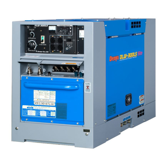
- Page 1 No. D48443 02204A Caution : Do not operate this machine before you thoroughly read and understand this manual. Always keep this manual near the machine. HEAD OFFICE 2-8-5 Nihonbashi-horidomecho, Chuo-ku, Tokyo, 103-8566 Japan +81 - 3 - 6861 – 1111 +81 - 3 - 6861 –...
-
Page 2: Table Of Contents
Page No. FOREWORD ----------------------------------------------------------------------- 1. SAFETY PRECAUTIONS ----------------------------------------------------------- 2. OUTLINE AND PART NAMES -------------------------------------------------------- 2-1 Outline Drawing and Name of Instrument ------------------------------------ 2-2 Name of Components -------------------------------------------------------- 2-3 Control Panel ------------------------------------------------------------- 3. TRANSPORTATION AND INSTALLATION ----------------------------------------------- 3-1 Caution in Transporting Machine ------------------------------------------ 3-2 Operating Angle ----------------------------------------------------------... -
Page 3: Foreword
◆ While the machine is placed for operation, please keep the instruction manual near the machine. ◆ For the detailed operation and maintenance of the ENGINE, please refer to the “Engine Operation Manual”. Your Machine ; Model No. : DLW-300LS Serial No. : [ NOTE ] [ NOTE ] [ NOTE ]... -
Page 4: Safety Precautions
The symbols shown below are used throughout this manual to call attention to and identify possible hazards. When you see the symbol, watch out, and follow the related instructions to avoid the hazard. Read and follow all Safety Standards. Only qualified persons should install, operate, maintain, and repair this machine. During operation, keep everybody, especially children, away. - Page 5 CAUTION : CAUTION : BATTERY ECTROLYTE CAN CAUSE In case the battery liquid EXPLOSIONS OR BURNS. (dilute sulfur acid) happens to come in contact Battery contains acid and generates with clothing or skin, you must immediately explosive gases. Handle battery carefully. rinse it out by using a lot of water.
- Page 6 CAUTION : CAUTION : WELDING CAN CAUSE FIRE OR Low voltage and frequency can EXPLOSION. damage electrical equipment such as Motors. ① Remove all flammables where flying Take caution or disconnect AC loads when sparks can strike. If this is not engine is starting or running with idle possible, tightly cover them with control switch in "ON".
-
Page 7: Outline And Part Names
2-1 Outline Drawing and Name of Instrument ① Control panel ⑥ Air intake ⑪ Oil drain ② Fuel tank inlet ⑦ Exhaust ⑫ Radiator inlet ③ Lifting hook ⑧ Ventilation ⑬ Lock ④ Door latch ⑨ Fuel drain ⑭ Ground Terminal ⑤... -
Page 8: Control Panel
2-3 Control Panel ① AC Voltmeter ⑩ e-Mode Selector Switch ② Welding Mode Selector Switch (VARIABLE, LOW/HIGH, HIGH) ③ Current Regulator ⑪ ※ 1-Phase AC output Receptacle ④ AC Circuit Breaker ⑫ ※ Earth Leakage Relay ⑤ Arc Force Regulator ⑬... -
Page 9: Transportation And Installation
3-1 Caution in Transporting Machine Caution : When transporting and lifting the machine, lift it at the lifting hook which is located at the center of gravity on the top panel. 3-2 Operating Angle Make sure the machine is placed on level foundation or ground. Do not operate the machine on place with inclination of more than 5 degrees, or engine damage will occur. -
Page 10: Preparations
3-3 Preparations This machine has undergone stringent factory tests and inspections to ensure the machine performs in accordance with its specifications, before been shipped to the end user. As with any piece of motorized machinery, excessive use of a brand new machine may shorten the life of the machine. -
Page 11: Battery
3-4 Battery Proper maintenance of the battery is extremely important to ensure smooth starting and long service life. Check the specific gravity, level of electrolyte and output voltage every 50 hours or once every month. [ NOTE ] [ NOTE ] [ NOTE ] [ NOTE ] : The electrolyte must always cover the plates. -
Page 12: Battery Cable Connection
3-5 Battery Cable Connection ◆ Make sure the battery cables are properly connected to battery terminal (+) and (-). [ NOTE ] : If the cable is connected incorrectly, damage to the electrical [ NOTE ] [ NOTE ] [ NOTE ] parts will result soon. -
Page 13: Lubricating Oil,Cooling Water And Fuel
4-1 Engine Oil Open air temp.(℃) ◆ The lubricating oil used influences engine performance, starting characteristic and ultimately the life of the engine. We recommend that the appropriate, good quality, lubricating oil be used. (1) We recommend that “CD class”lubricating oil be used ( API service grade ). -
Page 14: Fuel
4-3 Fuel (1) Use ASTM No.2 Diesel Fuel [ NOTE ] [ NOTE ] [ NOTE ] [ NOTE ] : If other than the recommended type of fuel is used, it can bring about a undesirable result to engine for its output performance, length of life, etc. -
Page 15: Fuel Consumption
4-4 Fuel Consumption (1) No Load High No Load (3000min (3600min (2000min Fuel Consumption (L/h) 1.28 1.65 0.72 (2) Load High[50Hz] Amperes (A) Fuel Consumption (L/h) 1.28 1.64 2.07 2.60 3.23 3.45 High[60Hz] Amperes (A) Fuel Consumption (L/h) 1.65 2.01 2.49 3.12 3.98... - Page 16 Fuel Consumption (60Hz) Fuel Consumption (60Hz) Fuel Consumption (60Hz) Fuel Consumption (60Hz) 4.50 4.00 3.50 High High High High 3.00 2.50 2.00 Variable Variable Variable Variable 1.50 1.00 0.50 0.00 DC Weld Amperes at 100% duty cycle [A] - 14 -...
-
Page 17: Engine Prestart Checks
◆ Check the positions shown under before starting. - 15 -... -
Page 18: Starting And Operating
◆ Before starting the machine, the pre-starting safety checks must be completed. In addition, do a general survey of the area surrounding the machine making sure the area is safe, air vents of the machine are not blocked and the exhaust can freely be discharged. - Page 19 (6) After the engine starts, let the machine idle 5 10 minutes to warm-up. And the engine rotates high speed for a few seconds immediately after the engine starts, if the “e Mode Selector Switch” is in VARIABLE or HIGH/LOW. [ NOTE ] [ NOTE ] [ NOTE ]...
-
Page 20: Stopping The Engine
(1) Turn the load side's circuit breaker to the“OFF”position. (2) Turn the circuit breaker on the machine to the“OFF”position and let the engine idle for five minutes, so as to allow the engine to cool down. After the five minutes idling period is over, turn the key to the “OFF”position. -
Page 21: Operating Precautions
7-1 Operating Precautions (1)Always read the meters and lamps on the control panel. ◆ While the machine is running, periodically check the readings of the meters on the control panel. Specifically, check that these meters show the machine in running correctly or the warning lamps are not on. -
Page 22: After Stopping
(5) Others ◆ While the machine is running, check the following: [ NOTE ] [ NOTE ] : Make a periodic check of the exhaust discharge, which will make the operator [ NOTE ] [ NOTE ] aware of any abnormalities in the exhaust discharge. [ NOTE ] : Check for leakage’s of lubricant oil, fuel, cooling water and exhaust [ NOTE ] [ NOTE ]... -
Page 23: Protection Device
7-4 Protection Devices This machine is equipped with the protection devices to prevent the abnormal states during its operation as shown in the table below. If the protection devices operate, stop the operation promptly and inspect or repair the abnormal point, or consult with our marketing section or service plant. - Page 24 ◆ FUSE The engine wiring system has its own fuse. If this fuse has blown, check the wiring to determine if there are any problems. If there are no apparent problems with the wiring, check to see if there are any alien substances in the wiring system. Repair any problems found in accordance with the Engine Manufacturer's Operation Manual.
-
Page 25: Operation Of The Welder
8-1 Welding Cable and Polarities (1) Connect securely the cable to the output terminals fitted under the control panel. Never allow the cable terminals to touch the other terminal or body steel. ※ Follow this illustration to connect the terminals. ※... -
Page 26: Selection Of Welding Cable
8-2 Selection of Welding Cable (1) The welding cable should be larger in size as it becomes longer or its current becomes higher. Prepare a cable having a suitable size by referring to the table below. Calculation for the table is based on the voltage drop of maximum 4V. Cable Selection Length 100 (A) - Page 27 Current Range and Engine Speed E Mode 50Hz 60Hz Selector Variable High Variable High Switch (2000 min (2300 3000 min (3000 min (2000 min (2300 3600 min (3600 min VARIABLE 30 280A 30 300A HIGH/LOW 30 280A 30 300A N/L, N/L, HIGH 30 280A...
-
Page 28: E Mode Operation
8-4 e mode operation (1) This function is capable of reducing noise, saving fuel and slashing CO in operating the engine at a low speed with no load or with a low Welding load. The operations at the e-mode switch positions are as follows: ①... -
Page 29: In Welding Operation
8-5 In Welding Operation During arc welding or arc cutting operation, be sure to use a cover glass to protect your eyes. It is very dangerous to operate without a protector such as mask, safety goggles or hand shield. - Reference - Numbers of bright degree of lens color depth of Applied electrode size... -
Page 30: Welding Mode Selector Switch And Arc Force Regulator
8-7 Welding Mode Selector Switch and Arc Force Regulator Use the “Welding Mode Selector Switch” and the “Arc Force Regulator“ to adjust welding characteristic according to the welding operation. This function is useful for peculiar welding operation. (1) CONSTANT CURRENT Control the welding output current according to the current setting even if the arc length is longer or shorter and it is unaffected by welding cable thickness or length. - Page 31 CONSTANT CURRENT Characteristic DROOP Characteristic Ex. Welding Current 100A Ex. Welding Current 100A Arc Force Regulation Center Point Soft Standard) Head Soft Head Standard) [ Ref. ] : graph below shows the calculation result for output current dropping rates in dropping characteristic. Fall due to cable drops with the welding regulation at the DROOP characteristic 280A et 38mm...
-
Page 32: Vrd(Voltage Reduction Device)
8-8 VRD (Voltage Reduction Device) This machine is equipped with the VRD function to prevent electric shock especially during operation performed in limited working space or in region with higher altitude or higher humidity. The VRD function is activated when you turn the “Voltage Reduction Switch”... -
Page 33: Ac Power Supply
8-9 AC Power Supply AC power supply This machine is provided with AC power supplies in addition to the welding power supply. Mount terminal to each tip (connection part) of the cable and cord without fail, and fasten the screw securely. (1) Be sure to turn off the circuit breaker for AC power source before connecting AC loads. - Page 34 (5) The following diagrams illustrate how to connect Single-phase loads to the generator’s output terminal. 3-Phase 4-Wire Output Terminal 3-Phase Load Use U,V,W for 200V/220V/380V/400V/415V/440V Single Phase Load Use O.U, O.V, O.W for 115V/127V/220V/230V/240V/254V Single Phase Load Use U.V, V.W, W.U for 200V/220V/380V/400V/415V/440V (6) If the three-phase power supply and single-phase power supply are used concurrently.
-
Page 35: Earth Leakage Relay(Option)
8-10 Earth Leakage Relay (Option) (1) Generator Description ◆ The machine is equipped with an earth leakage relay which has a current sensitivity of 30mA. The purpose of this relay is to detect any current leakage due to insulation failure of the load for example, while the generator is running. - Page 36 ② Grounding the Generator ◆ To ground the generator, the grounding rod supplied with the generator should be connect to the grounding terminal on the control panel. The grounding rod should be placed into the surface/ground. [ CAUTION ] : If the generator set is not ground. The earth leakage relay will not function.
-
Page 37: Maintenance
9-1 Routine Maintenance ◆ Be sure to stop engine before servicing. Remove dust and moisture from inside the machine and always keep it clean. Read the manual and give the machine correct inspection and maintenance. Inspect or maintenance the machine periodically in the interval time shown below. - Page 38 Check the tension of the fan belt. (Change if necessary) Check the gravity of Battery electrolyte. Change the air Clean the cleaner element. radiator. Adjust fuel injection nozzle. Change the fuel filter element and water separator element and the O-Ring. Clean the inside of the fuel tank.
-
Page 39: Engine Oil Filter
9-2 Engine Oil Filter (1) Change the Engine Oil Filter ① Remove the cartridge ( oil filter ) using the Filter Wrench. ② Insert the new cartridge. ③ Screw in the cartridge by hand. Once the gasket comes into contact with the face of the seal, tighten the cartridge (1 turns ) using the filter wrench. -
Page 40: Air Cleaner Element
9-4 Air Cleaner Element (1) Cleaning the Air Cleaner Element The air cleaner needs to be cleaned particularly if it has trapped a lot of dust and dirt ① Take the air element out. Clean the air element by passing an air current through the air element. -
Page 41: Troubleshooting
Trouble Cause Remedy No arcing or weak Loose or disconnected wires Visually check and repair arcing Poor contacting at wire terminal Pull the lead wire and check connection Generator Replace Control device (FE-50) Replace Transistor(IGBT) Replace Rectifier (Re1) Replace Current regulator(VR Replace DC reactor Replace... - Page 42 Trouble Cause Remedy Low power sudden No fuel Replenish shutdown of Air cleaner clogged Make clean element engine Faulty emergency shutdown switch. Check for oil quantity Check for water quantity Check fan belt Check radiator for clogging Abnormal color of Fuel of bad quality Change fuel emission...
-
Page 43: Storage Of Machine
◆ When storing, carry out the prescribed procedures for maintenance and inspection to keep the machine's life and performance. (1) Long Term Storage. Disconnect the battery cable (-) from the battery. (2) Battery Electrolyte Level. Replenish distilled water where the acid level is low. (3) Miscellaneous Checks. -
Page 44: Specifications
SPEC. / MODEL DLW-300LS Frequency (Hz) Rated Output (kW) 7.90 8.74 Rated Current Rated Voltage 30.4 31.2 Current Range Electrode (mm) φ2.0 φ6.0 Rated Speed (min 3000 3600 Duty Cycle Rated Output (kVA) 10.4 11.4 Rated Voltage Rated Current 30.0 27.3... -
Page 45: Outline Drawing
- 43 -... -
Page 46: Generator Wiring Diagram
- 44 -... - Page 47 - 45 -...
-
Page 48: Engine Wiring Diagram
- 46 -... - Page 49 - 47 -...
-
Page 50: Attachment
Engine Instruction Manual Instruction Parts List Manual Starter Key Door Key Fuse Earth Bar (option) - 48 -...
Need help?
Do you have a question about the DLW-300LS and is the answer not in the manual?
Questions and answers