Table of Contents
Advertisement
Quick Links
Advertisement
Table of Contents

Related Manuals for Cannon DIGI-TROLL 10


Summary of Contents for Cannon DIGI-TROLL 10
- Page 1 DIGI-TROLL 10 DIGI-TROLL 10 TS ELECTRIC DOWNRIGGERS USER MANUAL...
-
Page 2: Locating Your Serial Number
Minors may use this product only under adult supervision. ATTENTION: Your Cannon downnrigger should only be used for its intended purpose. Improper use will void the warranty and may be a safety risk. -
Page 3: Limited Warranty
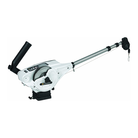
NOTE: Do not return your Cannon® downrigger or parts to your retailer. Your retailer is not authorized to repair or replace them. Major parts, such as the motor and main frame, must be returned to JOME in Mankato, Minnesota, or a Cannon® Authorized Service Center, for repair or replacement. - Page 4 ASSEMBLY & INSTALLATION DOWNRIGGER PARTS DESCRIPTION 1. Reel: This is used to spool the cable, available in lengths ranging from 150 to 400 feet. 2. Boom: This is used to extend the weight out from the body of the downrigger and has a pulley fixed to its end. Boom lengths range from 24 to 53 inches.
-
Page 5: Mounting Accessories
Decks thinner than 1/4” for stabilization (you will need to drill and countersink). Use a Cannon deck plate (sold separately - PN 2200693) to prevent defl ection and add INSTALLING THE INCLUDED MOUNTING bASE stability to decks thinner than 1/4”. Use the deck plate as a template to mark the hole locations. -
Page 6: Installing The Boom
ASSEMbLy & INSTALLATION Decks from 1/4” to 7/16” thick Where access to the underside of the deck is not available, the mounting base can be attached to the deck using wellnuts. Use the base as a base template to mark locations and drill four wellnut clearance holes. Mount Deck the base using four 1/4-20 x 1-1/2”... - Page 7 ASSEMbLy & INSTALLATION INSTALLING THE bOOM AND bALL HOOK 1. Remove the ball hook collar, ball hook, and 1/4-20 nut from the included hardware bag assembly. Thread the nut onto the ball hook, then thread the ball hook into the ball hook collar. Do not tighten yet. (Figure 1) 2.
- Page 8 ASSEMbLy & INSTALLATION INSTALLING THE SWIVEL HEAD 1. Locate swivel head assembly and then insert boom end post into end of the small tube of the boom assembly. (Figure 9) 2. Align hole in boom post with hole in small end tube. 3.
-
Page 9: Attaching The Rod Holder
ASSEMbLy & INSTALLATION ATTACHING THE ROD HOLDER The locking rod holder(s) incorporate a locking tooth design which can be easily adjusted every 15° with the soft grip knob. The symmetrical design will allow mounting of the rod holder on either side of the downrigger or two rod holders at the same time. - Page 10 NOTE: Use only straight cable, not kinked cable. 4. Slide the cushion over the top of the terminator and give it a test pull. The cable is now set to attach a Cannon Flash Weight™. ATTACHING THE LINE RELEASE (UNI-RELEASE) Close The Cannon Uni-Release attaches directly to the downrigger weight.
-
Page 11: Wiring Your Downrigger
7. Always make sure the boat is properly grounded to the water. This will help ensure proper PIC voltage on the cable and that the Short Stop will function properly. 8. The use of Cannon vinyl coated lead weights is recommended. 9. Use the trolling weight insulators supplied with your downrigger. This insulates your weight from the positive charge on the cable. - Page 12 Altering boat wiring should be completed by a qualifi ed technician. The following specifi cations are for general guidelines only: CAUTION: These guidelines apply to general rigging to support your Cannon Downrigger. Powering multiple Downriggers or additional electrical devices from the same power circuit may impact the recommended wire gauge. If you are using wire longer than that provided with your unit, follow the chart below.
-
Page 13: Wiring Diagram
WIRING THE DOWNRIGGER WIRING DIAGRAM COMMUNICATION HARNESS SONAR HARNESS KEYPAD RED WIRE (M+) BLACK WIRE (M-) RED WIRE GREEN WIRE (PIC) CIRCUIT BREAKER MOTOR RED WIRE BLACK WIRE POWER CABLE... - Page 14 USING A DIGI-TROLL TRANSDUCER USING AN OPTIONAL DIGI-TROLL TRANSDUCER By installing an optional Digi-Troll transducer accessory (1491072), the Digi-Troll 10 is able to display water depth and independently bottom track. INSTALLING THE OPTIONAL TRANSDUCER Proper transducer installation is critical to the performance of your Digi-Troll’ s depth tracking features. For best results, follow all mounting instructions carefully.
- Page 15 NOTE: The transducer cable MUST be connected before turning the unit on. WARNING: Connector removal or cable splicing voids the product warranty. Once the transducer is mounted and connected to your Digi-Troll 10, the display will show the bottom depth under SONAR DEPTH on the display (Figure 18).
- Page 16 NOTE: A negative depth indicates distance above the water surface. During programming of special features, the display is used to indicate various settings. The icons for the Digi-Troll 10 display are illustrated below. Icons will illuminate as they become applicable to function settings.
- Page 17 OPERATING THE DOWNRIGGER DIGI-TROLL 10 KEyPAD The Digi-Troll 10’ s keypad has eight keys located below the display: POWER The ON/OFF key functions: • Turn the Digi-Troll ON - Simply press and release. • Turn the Digi-Troll OFF - Press and hold power button for three seconds.
-
Page 18: Backlight Feature
PROGRAMMING THE DIGI-TROLL 10 The Digi-troll 10 contains up to eight menus that enable you to program and customize its operation. Any changes made using the menu system are automatically saved in permanent memory when the downrigger is turned off. - Page 19 In the bottom track mode, the Digi-troll 10 maintains the weight at a fi xed distance above the bottom. In order to avoid continuous weight adjustments due to minor changes in bottom depth and boat motion caused by wave action, you have the ability to adjust the responsiveness of the weight.
- Page 20 OPERATING THE DOWNRIGGER CyCLING MENU From the depth screen, press the MENU key once (or once from the Bottom Track screen if the transducer is connected) to enter this menu. The fi rst screen allows you to adjust the pause time of the weight between cycling movements. Press UP or DOWN to adjust.
- Page 21 OPERATING THE DOWNRIGGER UP SPEED MENU This menu lets you adjust the speed of the weight in the UP direction from 1 to 5 (1 slowest, 5 fastest) at all times except during the AUTO UP operation. AUTO UP is always at speed 5. Press the MENU key three times from the depth screen or once from the cycle menu.
-
Page 22: Units Menu
USING PROGRAMMAbLE DEPTHS The Digi-troll 10 allows you to program and store up to fi ve depths for quick movement of the weight without having to manually hold the DOWN key until the desired depth is reached. When in the (default) depth screen, simply press the Select key until the required depth memory is displayed. - Page 23 OPERATING THE DOWNRIGGER DIGI-TROLL FACTORy SETTINGS Your Digi-troll 10 was shipped with the following factory settings so that you can use your downrigger immediately without further programming. DEPTH MEMORy SETTINGS 25 feet 50 feet 75 feet 100 feet 150 feet...
-
Page 24: Manual Descent
Cannon’ s electric downriggers offer fi shermen a big advantage in being able to stabilize and control the positive charge around their boat. Because of the composite construction of the frame, Cannon downriggers are insulated from your boat’ s hull charge. - Page 25 OPERATING THE DOWNRIGGER How the Positive Ion Control System Works The PIC system uses an internal circuit that passes the voltage through the drive train of the Digi-Troll to the shaft. The shaft contacts the cable by means of a ball bearing, spring and, lastly, a one direction button head screw. Care must be taken to ensure contact between the cable and the screw when replacing the cable.
- Page 26 The farther the weight is behind you, the shallower the weight is. The following charts provide you with blowback information for three sizes of Cannon downrigger weights pulled at three different speeds with no lures attached and with no current. Current drag, water salinity and the use of non- Cannon products will affect your actual trolling depth.
- Page 27 REMOVABLE SPOOL COVER REMOVAbLE SPOOL COVER Your new downrigger comes with a removable spool cover. By removing this cover, you are able to gain easy access to your spooled cable and easy spool removal. This feature allows you to easily access tangled line, get it repaired and get you back into action quickly.
- Page 28 MANUAL CRANK HANDLE USING THE INCLUDED POWER LOSS MANUAL CRANK HANDLE In case of a dead battery, your downrigger comes equipped with a power loss manual crank handle. This handle allows for the retrieval of your weight should you lose power or have an electrical failure. To utilize the handle follow the below steps.
-
Page 29: Troubleshooting
TROUBLESHOOTING 1. In the UP or AUTO-UP mode the downrigger stops periodically but the display stays on or the circuit breaker trips repeatedly. • Low battery. The battery voltage at the power cord is less than 11.5 volts (measure with a volt meter while the downrigger is pulling up the weight). -
Page 30: Parts Diagram
PARTS DIAGRAM DIGI-TROLL 10 ELECTRIC DOWNRIGGER This page provides Cannon® WEEE compliance disassembly instructions. For more information about where you should dispose of your waste equipment for recycling and recovery and/or your European Union member state requirements, please contact your dealer or distributor from which your product was purchased. -
Page 31: Parts List
2373450 SCREW-#8-18 X 3/8 THD* (SS) 3391955 BASE-MOUNT, MAG ST 3396510 LENS-WINDOW 3390101 KNOB-CANNON, SOFT GRIP 3394019 KEYPAD, DIGI-TROLL 10 3393000 RING, RETAINING, 1/4” SHAFT 3396603 SEAL PLATE, DT10 3991904 ASSY-CNN, ROD HOLDER 700176 CON XCAP MINI-CON PANEL MOUNT 3394200... - Page 32 PARTS DIAGRAM DIGI-TROLL 10 TS ELECTRIC DOWNRIGGER This page provides Cannon® WEEE compliance disassembly instructions. For more information about where you should dispose of your waste equipment for recycling and recovery and/or your European Union member state requirements, please contact your dealer or distributor from which your product was purchased.
- Page 33 SCREW-#8-18 X 3/8 THD* (SS) 3393000 RING, RETAINING, 1/4” SHAFT 3396510 LENS-WINDOW 3991904 ASSY-CNN, ROD HOLDER 3394019 KEYPAD, DIGI-TROLL 10 3394200 ARM, DUAL AXIS-ROD HOLDER 3396603 SEAL PLATE, DT10 3392033 TUBE, DUAL AXIS RD HLDR 700176 CON XCAP MINI-CON PANEL MOUNT...
-
Page 34: Environmental Compliance Statement
COMPLIANCE STATEMENTS ENVIRONMENTAL COMPLIANCE STATEMENT: It is the intention of JOME to be a responsible corporate citizen, operating in compliance with known and applicable environmental regulations, and a good neighbor in the communities where we make or sell our products. WEEE DIRECTIVE: EU Directive 2002/96/EC “Waste of Electrical and Electronic Equipment Directive (WEEE)”... -
Page 35: Recommended Accessories
RECOMMENDED ACCESSORIES ROD HOLDERS & TRACK SySTEMS Incredible versatile rod holders, rock-solid bases and plates. It’ s everything you need to rig your boat up to fit the way you fish - and you can mount it all up on our track system, which features interchangeable components made of high-strength aluminum.
Need help?
Do you have a question about the DIGI-TROLL 10 and is the answer not in the manual?
Questions and answers