Table of Contents
Advertisement
Quick Links
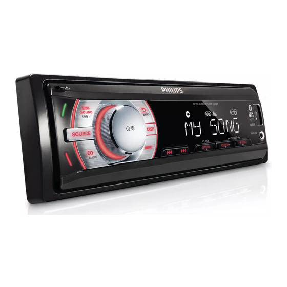
Bluetooth Car audio system
TABLE OF CONTENTS
Technical specification .................................................1-2
Version variation ..........................................................1-2
Service measurement setup.........................................1-3
Service aids ................................................................1-4
Instructions on CD playability ...............................2-1..2-2
Set Block diagram ....................................................... 3-1
Set Wiring diagram ...................................................... 4-1
Disassembly diagram .................................................. 5-1
Main board
Circuit diagram ...............................................6-1..6-2
Layout diagram . ..............................................6-3..6-4
Mechanical Exploded view ......................................... 7-1
Copyright 2010 Philips Consumer Electronics B.V. Eindhoven, The Netherlands
©
All rights reserved. No part of this publication may be reproduced, stored in a retrieval system or
transmitted, in any form or by any means, electronic, mechanical, photocopying, or otherwise without
the prior permission of Philips.
Published by LX 1027 Service Audio
Version 1.0
Printed in The Netherlands
Subject to modification
Page
CE150/
55/98
3141 785 35300
Advertisement
Table of Contents

Related Manuals for Philips CE150


Summary of Contents for Philips CE150
-
Page 1: Table Of Contents
Bluetooth Car audio system CE150/ 55/98 TABLE OF CONTENTS Page Technical specification ..........1-2 Version variation ............1-2 Service measurement setup.........1-3 Service aids ..............1-4 Instructions on CD playability .......2-1..2-2 Set Block diagram ............3-1 Set Wiring diagram ............4-1 Disassembly diagram ..........5-1 Main board Circuit diagram ..........6-1..6-2 Layout diagram ..........6-3..6-4 Mechanical Exploded view ......... 7-1 Copyright 2010 Philips Consumer Electronics B.V. Eindhoven, The Netherlands © All rights reserved. No part of this publication may be reproduced, stored in a retrieval system or transmitted, in any form or by any means, electronic, mechanical, photocopying, or otherwise without the prior permission of Philips. 3141 785 35300 Published by LX 1027 Service Audio... -
Page 2: Technical Specification
• Sound Enhancement: Dynamic Bass Boost, MAX • Sound • Output power (MAX): 50Wx4 channels • Output power (RMS): 22Wx4 channels (4 ohms, 10% T.H.D.) VERSION VARIATION Type /Versions: CE150 Service policy Board in used: TUNER BOARD MAIN BOARD Type /Versions: CE150 Features Feature diffrence RDS &... - Page 3 MEASUREMENT SETUP Tuner FM Bandpass LF Voltmeter 250Hz-15kHz e.g. PM2534 e.g. 7122 707 48001 RF Generator e.g. PM5326 S/N and distortion meter e.g. Sound Technology ST1700B Use a bandpass filter to eliminate hum (50Hz, 100Hz) and disturbance from the pilottone (19kHz, 38kHz). Tuner AM (MW,LW) Bandpass LF Voltmeter...
-
Page 4: Service Aids
SERVICE AIDS WARNING All ICs and many other semi-conductors are susceptible to electrostatic discharges (ESD). Careless handling during repair can reduce life drastically. When repairing, make sure that you are connected with the same potential as the mass of the set via a wrist wrap with resistance. Keep components and tools also at this potential. -
Page 5: Instructions On Cd Playability
2 - 1 INSTRUCTIONS ON CD PLAYABILITY Customer complaint "CD related problem" Set remains closed! check playability playability ok ? For flap loaders (= access to CD drive possible) "fast" lens cleaning cleaning method is recommended check playability playability ok ? Play a CD for at least 10 minutes check playability... - Page 6 2 - 2 INSTRUCTIONS ON CD PLAYABILITY PLAYABILITY CHECK LIQUID LENS CLEANING Before touching the lens it is advised to clean the surface of the lens by blowing clean air over it. For sets which are compatible with CD-RW discs This to avoid that little particles make scratches on use CD-RW Printed Audio Disc ....7104 099 96611 the lens.
-
Page 7: Set Block Diagram
3 - 1 3 - 1 SET BLOCK DIAGRAM... -
Page 8: Set Wiring Diagram
4 - 1 4 - 1 SET WIRING DIAGRAM... -
Page 9: Disassembly Diagram
5 - 1 5 - 1 SET DISASSEMBLY DIAGRAM DISASSEMBLY INSTRUCTIONS Dismantling the car audio system and the front cabinet 1) Press to open the panel, then uninstall it from the chassis 2) Remove the screw as "A" indicated to get the top cover off 3) Remove 6 screws as indicated to lossen the front panel PUSH PUSH... -
Page 10: Circuit Diagram
6 - 1 6 - 1 CIRCUIT DIAGRAM - MAIN BOARD PART 1... - Page 11 6 - 2 6 - 2 CIRCUIT DIAGRAM - MAIN BOARD PART 2...
-
Page 12: Layout Diagram
6 - 3 6 - 3 LAYOUT DIAGRAM - MAIN BOARD COMPONENT SIDE... - Page 13 6 - 4 6 - 4 LAYOUT DIAGRAM - MAIN BOARD COPPER SIDE...
- Page 14 7 - 1 7 - 1 EXPLODED VIEW DIAGRAM 6506 6505 6501 6503 6502 6504 PL01...