Table of Contents
Advertisement
MICOM SWING SW & SWSP
Installation Manual
MICOM AUTODOOR
Automatic Swing Door Operator
Model: MICOM SWING
Model SW & SWSP
Original Instructions
INSTALLATION MANUAL
The installation instruction detailed within are soley for profesional installers and not intended to be
handed over to the end user.
OSAKA – JAPAN
www.micomautodoor.com
vers.0001
Page 1
Advertisement
Table of Contents

Summary of Contents for Micom SWING SW
- Page 1 MICOM SWING SW & SWSP Installation Manual MICOM AUTODOOR Automatic Swing Door Operator Model: MICOM SWING Model SW & SWSP Original Instructions INSTALLATION MANUAL The installation instruction detailed within are soley for profesional installers and not intended to be handed over to the end user.
-
Page 2: Table Of Contents
FIXING INTRODUCTION SET AND ADJUST ARTICULATED ARM (PUSH) SET SLIDING ARM (PULL) SET UP TENSION STRING ADJUST OPENING LIMIT LEVER OPERATION OF THE MICOM SWING-SW & SP SYSTEM START UP. SELF-LEARNING NORMAL OPERATION ELECTRICAL FAULT ERRORS CONNECTIONS CONNECTION TO THE ELECTRICAL NETWORK... - Page 3 MICOM SWING SW & SWSP Installation Manual 12.2 PROGRAMMING MENU 12.2.1 Enter into the programming menu 12.2.2 Modify the programming parameter 12.2.3 Exit the programming menu and save the modifications 12.2.4 Programming example 12.2.5 Programming RESET PROGRAMMING PARAMETRES PROBLEM SOLVING. ERROR TABLE...
- Page 4 Control Unit. Failure to comply will result in loss of warranty. Installation and maintenance of this product can be performed by MICOM authorized personnel only. Before plugging in the 3-way connector (power on), make sure that no objects obstruct the travel of the automatic door.
- Page 5 MICOM SWING SW & SWSP Installation Manual IMPORTANT SAFETY NOTICE!!! When the door starts for the first time, it will automatically perform a series of opening and closing cycles (normally between 3 to 5 times) – Known as teaching or self-learning mode.
-
Page 6: Introduction
SW: Power Close SWSP: Spring Close The MICOM SWING is a non handed swing door operator system is to be utilized for automatic swinging pedestrian doors. It is suitable for Single and Double applications. Its small size and attractive housing design will compliment the aesthetics of any door. MICOM SWING SW & SWSP is very compact, durable and high-quality automatic swing door operator system. - Page 7 MICOM SWING SW & SWSP Installation Manual 2. TECHINCAL SPECIFICATION MICOM SWING SW MICOM SWING SWSP Closure with spring Arm system Push (Articulate) and Pull (Slide) Push & Go Yes (Adjustable) Power 230/110VAC 50,60Mhz 2Amp Opening speed 15-75deg/sec. (Adjustable) Weight of operator...
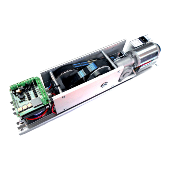
- Page 8 MICOM SWING SW & SWSP Installation Manual 3. COMPONANT PARTS Exterior views of the operator Interior view of the operator Page 8...
-
Page 9: Components
MICOM SWING SW & SWSP Installation Manual 4. PARTS LIST 4.1 List of components and operators Nº Components Reference Description Image 01 Sliding arm (pull) 2002277 Transmits the force of the mechanism to the For MI-SW-Pull door. Normally this is... - Page 10 MICOM SWING SW & SWSP Installation Manual 25mm BELT for MICOM 2002271 Belt Reduction Gear SWING -SW 09 Front cover for MICOM 2002274 Extruded Aluminum SWING -SW 10 Control unit for MICOM 2002269 Microprocessor Control SWING -SW Feed source for MICOM...
- Page 11 MICOM SWING SW & SWSP Installation Manual 4.2 Identification of Operators Nº Operators Reference Description Image A1 MICOM SWING 2002279 SW-Push Operator for swing doors with articulated arm A2 MICOM SWING 2002280 SW-Pull Operator for swing doors with sliding A3 MICOM SWING...
-
Page 12: Installation Of The Operator
MICOM SWING SW & SWSP Installation Manual 5. INSTALLATION OF THE OPERATOR 5.1 Preperation - Required tools Allen key. Sizes: ● 2’5 ● ● Spanner. Sizes: ● ● Phillips screwdriver. Sizes: ● ● Flat Screwdriver. Sizes: ● Drill bit for wall/concrete. Sizes: ●... - Page 13 MICOM SWING SW & SWSP Installation Manual 5.2 Prepare Operator ● Unpack the operator with care. ● Remove the central screw from the front cover Remove screw with 2’5 Allen key 1. Remove the front cover with care 2. Loosen the screw at the end of the reel so that this can move or turn easily.
-
Page 14: Fixing
MICOM SWING SW & SWSP Installation Manual 3. Orientate the operator. Before fixing the operator to the door frame or wall, we should study the orientation of the same, which can be: Normal or Reversed. Reverse Position Normal Position The orientation of the operator depends on the following factors: ... -
Page 15: Introduction
MICOM SWING SW & SWSP Installation Manual There are two ways to know how to orientate the operator: A. By Motor Pivot Direction: Motor Pivot Direction Motor Pivot Direction A. One method consists of turning the motor’s pivot manually. We can use the operator arm B. - Page 16 MICOM SWING SW & SWSP Installation Manual ● When the operator with an articulated arm (push) is fixed, a security distance should be used so that the arm does not hit against the door frame. Clearance or security distance with respect to the door frame.
- Page 17 MICOM SWING SW & SWSP Installation Manual 6.2 Fix and Adjust to Articulated (Push) Arm In order to fix and adjust the articulated arm: Separate the two parts of the arm joints. In order to separate them, you will have to remove the security ring.
- Page 18 MICOM SWING SW & SWSP Installation Manual Introduce joint 1 (socket) into joint 2 (plug) (see the following figure). Join “Part A” with “Part B” (see following figure).This will be achieved by screwing it in. Close the door and keep it closed until the arm has been installed.
- Page 19 MICOM SWING SW & SWSP Installation Manual 6.3 Fixing Slide Arm (Pull) In order to fix and adjust the sliding arm: 1. Remove the end covers to be able to work freely. 2. Introduce Part_B into Part_A, for one of its extremes.
- Page 20 6.4 Set up of the Tension Spring MICOM SWING SPSW has a door-closing system. In order for this to function perfectly, the tension spring must be pre-loaded. This load can be higher or lower depending upon the size/weight of the door panel or the clients’...
- Page 21 MICOM SWING SW & SWSP Installation Manual 6. After assigning a value to F, wait for the motor to stop turning (normally no more than a minute). When the motor stops, close the door and fix the arm to the motor pivot.
-
Page 22: Start Up. Self-Learning
7. OPERATION OF MICOM SWING SW & SWSP UNIT 7.1 Start Up and Self Learning IMPORTANT NOTICE: When the MICOM SWING SW & SWSP system starts up for the first time, the self-adjustment process will start for the system. This process will carry out an opening and closing cycle to find the actual length of the door stroke. - Page 23 MICOM SWING SW & SWSP Installation Manual Every time that important changes take place on the automatic door, such as: change of position of the stoppers, change to the size of the panels or change to the weight of the panels, in these cases you always have to do a “RESET”...
-
Page 24: Electrical Fault
When the electricity supply fails and if the operator is not equipped with a battery system: - with the MICOM SWING-SW model will stop working. - with the MICOM SWING-SWSP model the door will only close. 7.4 Errors A case could occur where the system has suffered a problem and therefore would cease to function correctly, e.g. -
Page 25: Connections
MICOM SWING SW & SWSP Installation Manual 8. CONNECTIONS 8.1 Connection to the Electrical supply The control unit can work at 230V or 110V, depending on client requirements. The feed power is 230V when it leaves the factory but the system can be configured to work at 110V; only a small modification has to be carried out inside of the feed supply (contact us for more details). - Page 26 MICOM SWING SW & SWSP Installation Manual 8.2 Internal Basic Connections Connection from the transformer to the feed supply. The connection from the transformer to the supply should be done with an 8-wire cable. This connection takes place in the factory and the technician should only have to do it in the event of a breakdown or when having to replace components (see the following figure for more details).
-
Page 27: Connection From Other Components
MICOM SWING SW & SWSP Installation Manual 9. Connection of other Components The EMICON card provides the function of inter-connecting the Control Unit to the various components: emergency battery, sensors, emergency button, control system, selectors, etc. The following are the connections: P2: 24Vdc Output. -
Page 28: P2 Connector. 24V Output
MICOM SWING SW & SWSP Installation Manual 9.1 P1 Connector. Access control card ST-500 connection The P1 connector links to the access control card, which allows control of the opening and closing of the door by means of remote controls, proximity key, tag, etc. - Page 29 MICOM SWING SW & SWSP Installation Manual 9.3 P3 Connector. Monitoring output (Security Sensor Monitor) The P3 connector is a communication output used by some presence detectors. It will check if the sensor is working correctly with this communication and therefore increasing the level of security for the automatic door (EN16005).
-
Page 30: P4 Connector. Emergency Stop (Emergency Stop)
MICOM SWING SW & SWSP Installation Manual NOTE: The Control Unit does not have the Monitoring function activated when it leaves the factory. In order to activate it, parameters 18, 19 or 35 need to be programmed - depending upon which sensor we want to Monitor in the Control Unit (see section “12.-PROMGRAMMING OF THE... - Page 31 MICOM SWING SW & SWSP Installation Manual This input has 5 working modes: Value 0 = No Lock Fitted (recommended when using Push&Go) Value 1 = Automatic Bolt unlocked with 12/24Vdc; and locked with 0V. * Value 2 = Automatic Bolt unlocked with 0V; and locked with 12/24Vdc. * Value 3 = Automatic Bolt unlocked with 12/24Vdc;...
- Page 32 MICOM SWING SW & SWSP Installation Manual In the event that the E-lock used should have polarity, the connection has to be carried out as follows Note: If the E-Lock product has no polarity, then connections are free 9.8 P12 Connector. Supply for E-Lock or automatic bolt 12Vdc (Lock) The P12 connector has the same qualities as the P6.
-
Page 33: P9 Connector. Internal Movement Sensor (Internal Sensor)
MICOM SWING SW & SWSP Installation Manual 9.9 P9 Connector. Internal movement sensor (Internal Sensor) The P9 connector is used to connect a motion sensor. The connector consists of 4 poles: ● Two poles are used to supply the sensor. The output is 24V DC. - Page 34 MICOM SWING SW & SWSP Installation Manual Its connection is identical to that of the P9 connector, except that it can be carried out in the P8 connector. 9.11 P10 Connector: Closing Safety Sensor 1 (Security 1) The P10 connector is used to connect the security sensor (or presence sensor) which protects from possible obstruction in the door closing movement.
- Page 35 MICOM SWING SW & SWSP Installation Manual In the event of needing more than one security sensor with NC (Normally Closed) contacts there needs to be a connection in series with the signal sensors, just as can be seen in the following figure: 9.12...
- Page 36 MICOM SWING SW & SWSP Installation Manual 9.13 P7 Connector: Selector A (Switch in three positions) The P7 connector connects the selector on the side of the operator. This selector has three positions, which are: HOLD OPEN - This mode allows the door to stay open.
-
Page 37: P11 Connector: Selector Switch B (Digital)
MICOM SWING SW & SWSP Installation Manual 9.14 P11 connector: Selector B (Digital) The P11 connector connects a Digital Selector. In order to change the function mode of the automatic door and keep it in its memory. The connection is by a 4- wire cable. Please be careful in the connection because these cable hasve polarity. - Page 38 MICOM SWING SW & SWSP Installation Manual Operating Modes The Selector B (Digital) has 6 buttons, giving various working modes. It also has 6 LED indicators that show the current working mode. All of the working modes available are as follows: “Close”...
- Page 39 MICOM SWING SW & SWSP Installation Manual resume the same state as to prior to the power cut. In order to activate the WITH MEMORY mode, the ‘Automatic’ button must be pressed down for 5 seconds. Note: This programming mode has been implemented by the factory.
-
Page 40: Problems
MICOM SWING SW & SWSP Installation Manual 11. PROBLEMS 11.1 Interference NOTICE: In certain automatic doors installations it could require to wire cables together. This should never be done. It is important to keep sensor and function selector cables apart from mains power cables. -
Page 41: Introduction
MICOM SWING SW & SWSP Installation Manual 12. PROGRAMMING THE CONTROL UNIT 12.1 Introduction The Control Unit has an area dedicated to programming of distinctive parameters of the automatic door, such as: speed, opening time, brake power, etc. The programming is carried out via a LED display and 3 buttons, as shown in the following image. - Page 42 MICOM SWING SW & SWSP Installation Manual 12.2.3 Exit Programming Menu & Saving Modifications In order to exit the programming menu and save all the changes carried out, you must do the following: ● Go into the “00”parametre ● Press “ENTER”...
- Page 43 MICOM SWING SW & SWSP Installation Manual 12.2.5 RESET of the programming The control unit retains programming parameters in its memory and also other important details such as door operation setting from the learning process as well as braking adjustments etc…...
- Page 44 MICOM SWING SW & SWSP Installation Manual 13. PROGRAM PARAMETERS Parameter Description Adjust Factory Value Setting Exit programming Display screen rotation From 0 to 2 Value 0 = Automatic Value 1 = Normal Value 2 = Reserve Automatic Closing Timer...
- Page 45 MICOM SWING SW & SWSP Installation Manual Opening Deceleration From 0 to 9 Value 0 =Gradual Deceleration Value 9 = Rapid Deceleration Closing Deceleration From 0 to 9 Value 0 = Gradual Deceleration Value 9 = Rapid Deceleration Static Opening Force...
- Page 46 MICOM SWING SW & SWSP Installation Manual Value 2 = At 10º of closing Value 3 = At 15ºof closing Value 4 = At 20ºof closing Value 5 = At 25º of closing Value 6 = At 30º of closing...
- Page 47 MICOM SWING SW & SWSP Installation Manual Safety Sensor Input (Closing Side) 0 or 1 Value 0 = NO (Normally Open) Value 1 = NC (Normally Closed) Emergency Stop Input 0 or 1 Value 0 = NO (Normally Open) Value 1 = NC (Normally Closed)
- Page 48 MICOM SWING SW & SWSP Installation Manual Value 4 = High (recommended in areas with high winds) Value 5 = Very High (recommended in areas with high winds) Lock Delay From 0 to 1 Value 0 = 0,5 second Value 1 = 1 second...
- Page 49 MICOM SWING SW & SWSP Installation Manual Value 2 = The master door will open before the slave door and they close at the same time Function of the Channel 2 receptor From 0 to 2 Value 0 =Close the door immediately Value 1 = Activates and deactivates the Push &...
- Page 50 MICOM SWING SW & SWSP Installation Manual For example, to show the number 2500, it will appear as follows: ● “2” ● ….. ● ”5” ● ….. ● ”0” ● ….. ● ”0” ● ….. Value 2 = Shows the charge level of the battery.
- Page 51 MICOM SWING SW & SWSP Installation Manual ● ”0” ● ….. Value 4= Software Version. Value 5= Test Monitoring Output (activates for 4 seconds). Value 6= Indicates the strength charged on the spring. Value 7= Indicates, approximately, the weight of the door panels.
- Page 52 MICOM SWING SW & SWSP Installation Manual 14. TROUBLE SHOOTING – ERROR TABLE When the automatic door finds itself in a state of error, a message will appear on the Control Unit display screen which indicates the type of error that has occurred. An acoustic signal will be heard.
- Page 53 MICOM SWING SW & SWSP Installation Manual sensor - If the problem persists, replace the security sensor with a new (monitoring one. the opening) _ _ _ _ _ __ Broken belt - Check the good working state of the motor belts. If the belt is or reducer of damaged, replace it with a new one.
- Page 54 MICOM SWING SW & SWSP Installation Manual doesn’t have any space. _ _ _ _ _ _ _ _ Error in the - Check that the internal movement sensor connected has the _ _ _ _ __ supervision supervision option activated (Monitoring).
- Page 55 MICOM SWING SW & SWSP Installation Manual The door doesn’t open and - Check that the opening security sensor is not activated or always remains closed defective. -Check that the function selector is not on “close” or “manual” mode. - If the function selector has a lock and key, place the key on the ON position.
- Page 56 MICOM SWING SW & SWSP Installation Manual If considerable force is Assign value 0 to the following parameters: 10, 15, 29 required to push the door when the Push&Go option is Assign value 1 to parameter 11 in use Page...
- Page 57 MICOM SWING SW & SWSP Installation Manual 15. MAINTENANCE The automatic doors require servicing and maintenance. It is essential to be aware of the importance in carrying out maintenance in order to enjoy a secure and trustworthy product. The adjustments and service will ensure a safe and correct function of the automatic doors.
Need help?
Do you have a question about the SWING SW and is the answer not in the manual?
Questions and answers
Comment configurer micom swsp entre maître et esclave
To configure the MICOM SWING SW in master and slave mode, adjust the Double Door (Dual) Function setting:
1. Set parameter 37 (Double Door Function):
- Value 0: Not defined (Single door mode)
- Value 1: Master mode
- Value 2: Slave mode
2. Set parameter 38 (Double Door Closing Sequence):
- Value 0: Both doors open at the same time.
- Value 1: The master door opens first and closes after the slave door.
- Value 2: The master door opens before the slave door, and both close at the same time.
These settings define the door operation in a double-door system.
This answer is automatically generated
@Mr. Anderson