
Summary of Contents for EverExceed 6K
-
Page 1: User Manual
EverExceed PowerLead2 Series UPS (6-10KVA)(HV model) User Manual www.everexceed.com PowerLead2 Series 6-10kVA UPS User Manual... - Page 2 IMPORTANT SAFETY INSTRUCTIONS SAVE THESE INSTRUCTIONS This manual contains important safety instructions. Read all safety and operating instructions before operating the uninterruptible power systems (UPS). Adhere to all warnings on the unit and in this manual. Follow all operating and user instructions. This equipment can be operated by individuals without previous training.
-
Page 3: Table Of Contents
Contents CONTENTS IMPORTANT SAFETY INSTRUCTIONS ............1 1. PRODUCT DESCRIPTION ................3 1.1 E ................... 3 LECTROMAGNETIC OMPATIBILITY 1.2 F ............................4 EATURES 1.3 M ............................4 ODELS 1.4 A ........................... 4 PPEARANCE 1.5 S ........................6 YSTEM DESCRIPTION 1.5.1 Transient Voltage Surge Suppression (TVSS) and EMI/FRI Filters ..6 1.5.2 Rectifier/Power Factor Correction (PFC) Circuit ......... - Page 4 Contents 4. OPERATION ....................22 4.1 O ........................22 PERATION 4.2 P ......................... 22 ARALLEL PERATION 5. CONTROL AND COMMUNICATION ............24 5.1 SNMP C ..........................24 5.2 D ..........................24 ONTACT 5.3 EPO ..............................25 5.4 RS485 ............................. 25 6.
-
Page 5: Product Description
Product Description 1. Product Description Congratulations on your choice of the UPS uninterruptible power system(UPS), the UPS comes in nominal power ratings of 6000VA,10000VA. It is designed to provide conditioned power to computers and other sensitive electronic equipment. This chapter gives a brief description of the UPS, including the UPS features, models, appearance, operating principle and specification. -
Page 6: Features
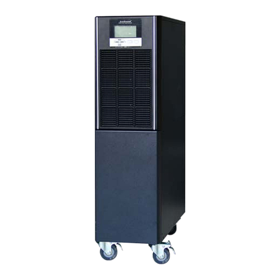
Failure waveform record function help to solve problem quickly 1.3 Models Available models are shown as Table1-1: Table 1- 1: Models Model Nominal Power Model Norminal Power 6K long backup 6000VA/6000W 10K long backup 10000VA/10000W 6K standard backup 6000VA/6000W 10K standard backup 10000VA/10000W 1.4 Appearance... - Page 7 Product Description Fig 1- 1: Front View USB(option) Parallel (option) RS232 Intelligent slot Reserved Terminal cover Cold start Input breaker button Bypass breaker Ground Cable protector Fig 1- 2: Rear View As shown in Fig 1-2, the rear panel provides the following compoentes and function: ...
-
Page 8: System Description
Product Description EPO: NC Parallel port: option Reserved: reserved for customer function, such as manual bypass, battery breaker, socket and so on Terminal cover Input breaker: surge proection Bypass breaker: surge proection Cable proetector: cable entry, fix cables, safety ... -
Page 9: Inverter
The converter includes boost circuit which is also used as PFC. 1.5.6 Battery The 6K/10K Standard include value-regulated, non-spillable, lead acid batteries inside. To maintain battery design life, operate the UPS in an ambient temperature of 15-25°C. 1.5.7 Static Bypass The UPS provides an alternate path for utility power to the connected load in the unlikely event of a UPS malfunction. - Page 10 Product Description charging the battery. BYPA TVS&RFI/E REC/PFC MI filter input BATT Fig 1- 4: Normal Mode Static Bypass Mode If inverter is failure or overload, UPS will transfer to bypass mode. Or press ON/OFF to transfer to bypass mode in normal mode. The load is feed by input power directly, and UPS can not protect load from surge.
- Page 11 Product Description BYPA TVS&RFI/E REC/PFC INVERTER MI filter input BATT Fig 1- 6: Battery Mode ECO Mode (only available for single unit) When UPS works in ECO mode, load is feed by bypass. Inverter is standby, charger is working normally. The efficiency is up to 98%, but UPS can protect the load from surge disturb. If input power is failure, UPS transfer to battery mode.
-
Page 12: Product Specification
Product Description BYPA TVS&RFI/E rectifier/PFC INVERTER MI filter input BATT Fig 1- 8: Self Aging Mode 1.7 Product Specification 1. General Specification Model 10KS 10KL Power Rating 6KVA/6KW 10KVA/10KW Frequency (Hz) 50/60 50/60 Voltage (176-288)VAC (176-288)VAC Input Current 36A max. 60A max Voltage 192VDC... - Page 13 Product Description Output Voltage Power Frequency Distortion Overload capacity Crest ratio Regulation Factor tolerance. 110% load: transfers Bypass mode after 60 minutes THD<1% 130% load: transfers ±0.1 Full load Bypass mode after 1 minute ±1% normal (Linear 150% load :transfers maximum Load) Bypass mode after 0.5 minute...
-
Page 14: Installation
1) Open the terminal block cover located on the rear panel of the UPS, please refer to the appearance diagram. 2) For 6k(L) UPS, it is recommended to select the UL1015 10AWG(6mm ) wire or other insulated wire which complies with AWG Standard for the UPS input and output wirings. -
Page 15: Operating Procedure For Connecting The Long Backup Time Model Ups With
Installation BAT+ BAT- OUT_L OUT_N IN_N IN_L Fig 2- 1: Terminal Block Wiring Diagram NOTICE:Make sure that the input and output wires and the input and output terminals are connected tightly. 6) The protective earth ground wire refers to the wire connection between the equipment which consumes electric equipment and the ground wire. -
Page 16: Connect Parallel Cables
Installation insulated wire which complies with UL Standard for the UPS battery wirings. The procedure of installing battery bank should be complied with strictly. Otherwise you may encounter the hazardous of electric shock. 1) A DC breaker must be connected between the battery pack and the UPS. The capacity of breaker must be not less than the data specified in the general specification. -
Page 17: Connect Communication Cables
Installation BATT1 INPUT BATT INPUT Fig 2- 2: Parallel Wiring Diagram 2.5 Connect Communication Cables Communication cable includes: USB cable and parallel communication cables. Connect USB cable: 1) Connect USB cable to USB port at the back panel of UPS shown as Fig 1-2 2) Connect USB cable to PCB Connect communication cables: If there are two UPS are paralleled, connect communication cables as Fig.2-3... - Page 18 Installation UPS 0# UPS 1# Fig 2- 3: 2 UPS Paralleled System If there are 2 UPS are paralleled, connect communication cables as Fig 2-4 UPS 0# UPS 1# UPS 2# Fig 2- 4: 3 UPS Paralleled System NOTICE: must set the UPS is parallel system as “parallel mode” via software according to “Annex A”...
-
Page 19: Controls And Indicators
Installation 3. Controls And Indicators Button LED indicators Fig 3- 1: Display Panel Description of Panel Controls Description 1.Press ON/OFF to start inverter when rectifier is OK NOTE Not available when UPS is set in automatically start mode ON/OFF 2.Press ON/OFF to shutdown inverter and transfer to bypass 3.Press ON/OFF to shutdown UPS completely when UPS is in battery mode 4.Press ON/OFF to confirm setting when in setting mode... - Page 20 Installation mode and bypass is normal, red—bypass fault, red flicker—bypass alarm Battery indicator: green—battery charge, green flicker—battery discharge, dark—battery is connected, red—battery fault, red flicker—battery alarm Output information Input information Bypass Load, alarm Battery Setting version, information indicator alarm code Fig 3- 2: LCD Menu Description of LCD Menu Menu...
- Page 21 Installation Menu Information to get detailed code list B: bypass input menu Others SETTING: LCD is in setting mode BYPASS: bypass conversion Press FUNC to check menu: description Page Page 1: INPUT voltage: 234VAC OUTPUT voltage: 220VAC Battery voltage: 259VDC LOAD : 13%.
- Page 22 Installation mode, “SETTING” on the bottom of LCD present and all LEDs flicks. Input rated Could select input voltage as voltage setting 200VAC/ 208VAC/ 220VAC/ 230VAC/ 240VAC, press FUNC to select, press ON/OFF to confirm selection and enter in next page Input rated Could select input frequency as...
- Page 23 Installation Charger current Charger current could be set as setting below: Standard model: 1A Long backup model: 1,2,3,4,5A Optional super charger: 1-10A Press FUNC to select, press ON/OFF to confirm and enter in next page Communication 0CC-MODBUS protocol setting 1CC-SNT Press FUNC to select, press ON/OFF to confirm and enter in next page...
-
Page 24: Operation
Operation 4. OPERATION 4.1 Operation Mode 4.1.1 Turn on the UPS in normal mode 1) After you make sure that the power supply connection is correct, and then close the battery breaker (this step only for long backup time model), after that close the main input and bypass input breaker. At this time the fans rotate and the UPS operates in Bypass mode. - Page 25 Operation Close external output CB1 and CB2 Close mains input breakers and bypass input breakers of UPS1 and UPS2, after about 2 minutes, UPSs works in parallel mode Close external battery breakers Turn on load. The load is now powered by parallel system. 4.2.2 Turn off Parallel System 1) Turn off the connected load.
-
Page 26: Control And Communication
Control and Communication 5. Control and Communication UPS includes several communication ports: RS232,EPO,SNMP card, USB, dry contact, RS485. NOTICE: Only one of SNMP card, dry contact and RS485 can be at the same time. Only one of RS232 and USB is available at the same time. 5.1 SNMP Card SNMP card is used to monitor the UPS via TCP/IP, user can check the UPS status, voltage and current on the internet. -
Page 27: Epo
Control and Communication mode mode. Utility Opened form common connection: utility input is failure failure UPS fail Bypass mode General alarm Battery low UPS is on 12~24VDC Remote shutdown Utility fail Fig 5- 2: Connect to External Power Supply 5.3 EPO The remoted EPO is located on the rear panel of UPS shown as Fig 1-2. -
Page 28: Maitenance
Maintenance 6. Maintenance This chapter includes battery maintenance, battery disposal and replacement, check UPS status and function. 6.1 Battery Maintenance The UPS only requires minimal maintenance. The batteries used for standard models are value regulated, sealed lead-acid, maintenance free battery. When being connected to the utility power, whether the UPS is turned on or not, the UPS keeps charging the batteries and also offers the protective function of overcharging and over-discharging. -
Page 29: Battery Replacement Procedures
Rated Parameters Set on LCD 6.3 Battery Replacement Procedures Press ON/OFF button to transfer to bypass mode Close the manual bypass breaker Remove both side covers from the UPS. Disconnect the battery wires one by one. Remove metal bars which are used to fasten batteries. Replace batteries one by one. -
Page 30: Trouble Shooting
Trouble Shooting 7. Trouble Shooting This chapter describes checking the UPS’s status. This section also indicates various UPS symptoms a user may encounter and provides a troubleshooting guide in the event the UPS develops a problem. Use the following information to determine whether external factors caused the problem and how to remedy the situation. - Page 31 Trouble Shooting If the faulty load is removed, please manually fault clear to restart UPS. Rectifier fault DC bus over voltage, low voltage, shorted or IGBT opened. Please manually clear the fault and if the fault is still on, please contact with local dealer Inverter fault Inverter voltage is abnormal, or inverter IGBT opened.
-
Page 32: Annex A. Parallel Setting
Trouble Shooting Annex A. Parallel Setting 1. Connect UPS1 with RS232 cable to PC. Connect UPS with monitoring software. 2. Enter in menu “ServSetting”, set System Mode as “Parallel” in the menu “System Setting”. 3. Set United Number as “2”, set System ID as “0”. Press “set” to confirm setting. 4. -
Page 33: Annex. B Mechanical Size
Trouble Shooting Annex. B Mechanical Size 1.6kVA long backup model 2.6kVA standard model 3. 10kVA long backup model PowerLead2 Series 6-10kVA UPS User Manual... - Page 34 Trouble Shooting 4. 10kVA standard model PowerLead2 Series 6-10kVA UPS User Manual...
-
Page 35: Annex C. Battery Run Time
Battery Run Time Annex C. Battery Run Time Standard battery pack includes 16 blocks 9AH batteries. Please refer to the table below for the battery runtime to configure battery packs. Pack’s Backup Time (mins) number 10KW NOTICE: Backup time of batteries is depending on other facts such as battery brand, working temperature, working time and so on, the table is calculated according to ideal situation.
Need help?
Do you have a question about the 6K and is the answer not in the manual?
Questions and answers