Advertisement
Quick Links
Advertisement

Summary of Contents for OrienTek T40
- Page 1 ORIENTEK T40 Optical Fiber Fusion Splicer User’s Manual...
-
Page 2: Safety Summary
Safety Safety Summary Summary Safety Safety Summary Summary The following general safety precautions must be observed during all phases of operation of this instrument. Failure to comply with these precautions or with specific warnings elsewhere in this manual violates safety standards of design, manufacture, and intended use of the instrument. -
Page 3: General Safety Information
General General Safety Safety Information Information General General Safety Safety Information Information � � � � AC/DC Adapter/Charger AC/DC AC/DC AC/DC Adapter/Charger Adapter/Charger Adapter/Charger The following voltage requirements must be met: 12.9V to 14V, 4.5A, positive core. Use of higher voltages may damage the product. - Page 4 Caution Caution Caution Caution � � � � AC/DC AC/DC AC/DC Adapter/Charger Adapter/Charger AC/DC Adapter/Charger Adapter/Charger Please use the AC/DC adapter/charger that supplied by our company. Use of another type of AC/DC adapter can damage the instrument. � � � � Battery Battery Battery Battery...
- Page 5 � � � � LCD 1. Don’t use any sharp device to press the touch screen. Don't pollute touch screen with any organic compound or organic contaminant such as heptanes, ethanol, toluene, cello solve acetate, hydrochloric acid, motor oil, diesel fuel etc.
- Page 6 Maintenance Maintenance Warranty Warranty Maintenance Maintenance and and Warranty Warranty Our company warrants this instrument against defects in material and workmanship for 18 months, battery for 3 months from the date of original shipment. From the date of original shipment. The warranty can become null and void if: The instrument has been misused, neglected, or damaged by accident.
- Page 7 Contents Contents Contents Contents Safety Safety Summary Summary ......................................i i i i Safety Safety Summary Summary............... General General Safety Safety Information Information ............................ii ii ii ii General General Safety Safety Information Information..........Caution ..............................iii iii iii iii Caution Caution Caution................
- Page 8 Chapter Chapter Chapter 1 1 1 1 General General General Information Information Chapter General Information Information The Optical Fiber Fusion Splicer (OFFS) is applied to fiber fusion splice, it can splice various types of optical fiber (core diameter:80-150μm) including single mode fiber, multi-mode fiber, dispersion shifted fiber.
- Page 9 Chapter Chapter Chapter 2 2 2 2 Special Special Special Terms Terms Chapter Special Terms Terms 2.1 SM Single Mode Fiber 2.2 MM Multimode Fiber 2.3 DSM Dispersion Shifted Fiber NZDSM 2.4 NZDSM NZDSM NZDSM Non-zero Dispersion Shifted Fiber Cleave Cleave Length Length...
- Page 10 in vertical direction signed by ‘X’ and ‘Y’. The text on the top of the screen is the index of used fusion parameter group. R e a d y SM 0 1 2 4 ℃ 4 3%RH 2 0 1 0-0 2-2 5 1 9:3 3 Figure 2-2 R e a d y S M 0 1...
- Page 11 parameters return to their initial status. Once reset, the Splicer is capable of splicing again. 2. 2. 2. 2.9 9 9 9 Alig Alig Alig Align n n n ment ment ment ment The operation is to adjust the two fibers, so that they are in the same direction.
- Page 12 Chapter Chapter Chapter 3 3 3 3 Technical Technical Technical Parameters Parameters Chapter Technical Parameters Parameters 3. 3. 3. 3.1 1 1 1 Fiber Fiber Fiber Requirements Requirements Fiber Requirements Requirements The OFFS can splice the fibers which accord with ITU-TG.651 ~...
- Page 13 � Temperature limits: -10°C~+50°C � Operating humidity: <95%RH(no condensing) � Windy speed: <15m/s � Storage temperature: -20°C~+60°C � Storage humidity: no condensing 3. 3. 3. 3.6 6 6 6 S S S S plice plice Loss plice plice Loss Loss Loss For those fibers recommended by ITU-T G.651 ~...
- Page 14 Chapter Chapter Chapter 4 4 4 4 Configuration Configuration Configuration Chapter Configuration The standard configuration of the OFFS as following table. Table 4-1 Name Picture Remark Optical Fiber Host Fusion splicer Carrying case Accessory Pump bottle Accessory Blower brush Accessory AC current cable Accessory AC power adapter...
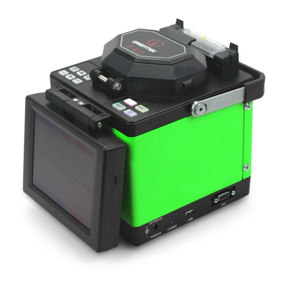
- Page 15 Chapter Chapter Chapter 5 5 5 5 S S S S tructure tructure tructure Panel Panel Chapter tructure and and Panel Panel Brief Brief introduction introduction introduction of of of of S S S S tructure tructure tructure 5.1 Brief Brief introduction tructure The portable fusion splicer which was specially designed is...
- Page 16 Introduction Introduction Introduction to to to to Panel Panel Panel 5.2 Introduction Panel 5. 5. 5. 5.2.1 Shield Shield 2.1 Shield Shield The shield is closed unless fibers are going to be put in. Close it before any keyboard operation. With a viewfinder mirror and a holding clamp for bare fiber in the V-groove, it can prevent dust and wind and provide vertical light for the microscope.
- Page 17 R E S E T P O W E R A U T O H E A T A R C/ + X-Y/- Figure 5-2 Table 5-1 Function Description This key is power, when it was pressed for P O W E R about 0.5 second;...
- Page 18 Table 5-2 Function Description Exit the current menu and return to the upper level or to the splicing interface (if in the main menu currently). Press to enter the next sub-level menu ; used to switch between the right and left fibers when adjusting motor, In the test menu, it confirms the start of a test.
- Page 19 Table 5-3 Function Description Press this key; the splicer accomplishes cleaning, gap adjustment, alignment, fusion A U T O splicing and loss estimating functions. The results will be displayed automatically on the screen. Press this key and the splicer will discharge for a short time between the two electrodes.
- Page 20 Introduction Introduction Introduction to to to to Port Port Port board board 5.4 Introduction Port board board Input/Output port is on the right side of the main body, as figure 5-3, the function are introduced in table 5-4. Figure 5-3 Table 5-4 Function Description Name...
- Page 21 Chapter Chapter Chapter 6 6 6 6 Installation Installation Installation and A A A A djustment djustment djustment Chapter Installation and djustment Open the shield and check whether are there dusty or the other eye winker (such as short fiber) in the fixture. Brush clean the V-grooves in one direction with an alcohol-soaked cotton swab.
- Page 22 Whether the V-groove is clean or not? If not, clean it. Whether the fiber end profile is good or unqualified? If unqualified, cleave the fiber again. Whether the fiber is a standard fiber or not? If not, replace it with a standard one. If the trouble is not included in the above lists.
- Page 23 Chapter Chapter Chapter 7 7 7 7 Basic Basic Basic Operation Operation Chapter Basic Operation Operation Power Power Connection Connection 7.1 Power Power Connection Connection Battery power and DC power were supplied to provide convenience, and the DC power was connected to the AC power through an adapter, please make sure the voltage of AC power is 110V- 240V! When the Fusion was connecting the DC power, the battery was charged.
- Page 24 “ “ “ “ Splice Splice Splice mode mode mode” ” ” ” : : : : Auto, semiauto, manual. Splice mode : Include CMOS setting, language selection, time “ “ “ “ Setup Setup Setup” ” ” ” Setup setup, tension test setting, and power save, restore factory settings.
- Page 25 menu menu menu as as as as following: following: following: The menu following: To save single-mode fiber splicing parameter groups. 10 groups in total: 01~ 09 which can be changed. To save multi-mode fiber splicing parameter groups. 10 groups in total: 01~ 09 which can be changed. To save dispersion shift fiber splicing parameter groups.
- Page 26 to enter menu of adjustment of splice parameters. Specification Specification Specification of of of of Splice Splice Splice Parameters Parameters Specification Splice Parameters Parameters All items in the parameters group as table 7-1. Parameter Modification: Use the key to move the cursor to the item that needs to be adjusted, and then it means this parameter could be modified.
- Page 27 Adjustment Adjustment Adjustment of of of of Splice Splice Splice Power Power 7.3 Adjustment Splice Power Power This part gives instructions on how to achieve low splice loss in different environment conditions. a) The recommended parameter group is decided according to the fiber gap of arc test.
- Page 28 Step 5: Set the other fiber in the same way. Put the shield down carefully. Note: Note: Note: Note: Set the other fiber in the same way. Put the shield down carefully. Fiber Wrong way to install Figure 7-7 b) The tip of the coating fiber should keep a distance from the bare fiber mount.
- Page 29 Splicing Splicing Operation Operation 7.6 Splicing Splicing Operation Operation There are three splicing modes for selection: Manual, Semi-auto and auto splicing mode. 7.6.1 7.6.1 7.6.1 M M M M anual anual anual splicing splicing mode mode 7.6.1 anual splicing splicing mode mode (1) Strip, clean and cleave the optical fibers.
- Page 30 whether the splicer automatically puts the two fibers end profiles to the screen center or not. We advise the user to take the auto and Semi-auto splicing mode except for special-type fiber. Estimated Loss 0.0 1d B 2 4 ℃ 4 3%RH 2 0 1 0-0 2-2 6 9:3 3 Figure 7-7 Tension Passed...
- Page 31 7.6.3 7.6.3 Auto Auto splicing splicing mode mode 7.6.3 7.6.3 Auto Auto splicing splicing mode mode "READY" is displayed on the screen. (1) Do the same steps as in section 7.6.1: (1), (2), (3), (4), (5), (6), (7). (2) Close the shield and the splicer will exercise Clean, Gap, Align, Fusion and Tension Test functions automatically.
- Page 32 Phenomenon Reason Resolve method Fiber Not Aligned Dust in the Clean V-groove V-groove. Fiber Diameter Do Arc Power Discharge power is Too Small test and adjust inappropriate. the current. Increase Splice parameter is discharge time or inappropriate. stuff length. Black Line Adjust the Splice parameter is current and the...
- Page 33 (1) Open the heater cover and the left and right fiber clamps of heater. (2) Move the protection sleeve to the center of the splice part. (3) Hold the fiber, tighten it lightly and then set the splice point in the center of the heater. (Do not let the fiber sag) Protect Sleeve Bare Fiber...
- Page 34 Chapter Chapter Chapter 8 8 8 8 Maintenance Maintenance Maintenance Chapter Maintenance Cleaning Cleaning 8.1 Cleaning Cleaning Keep the V-groove, electrode, microscope clean. The shield should be closed when the splicer is not used. 8.1.1 8.1.1 Cleaning Cleaning V-groove V-groove 8.1.1 8.1.1 Cleaning Cleaning V-groove...
- Page 35 lens can cause trouble in the image process and a big splice loss. (1) Turn off the power. (2) Use a cotton swap soaked with pure alcohol to clean the lens’s surface from center toward rim. (3) Turn on power. Make sure dust cannot be seen on the LCD screen.
- Page 36 wiping the lens with cotton stick (having been dipped in alcohol), move it in one direction instead of back and forth. (7) Keep the LCD screen away from the sun and high heat sources. (8) Turn off the power switch before power cable is connected.
- Page 37 Alarm Alarm indication indication abnormal abnormal remedy remedy 8.4 Alarm Alarm indication indication and and abnormal abnormal remedy remedy Table 8.1 Message Reason and Remedy There is dust on the V-groove... A fiber is OVER RUN detached from its V-groove. A fiber is dirty. The bare fiber is too short...
- Page 38 APPENDIX APPENDIX APPENDIX A A A A Test Test Test Adjustment Adjustment APPENDIX Test and and Adjustment Adjustment A. A. A. A.1 1 1 1 Entering Entering Entering Sub-menu Sub-menu Entering Sub-menu Sub-menu Follow the instruction of section 7.4, locate two fibers with qualified end profiles before operation and close the shield.
- Page 39 Now the screen displays as Figure A-2. Arc Test 2 4 ℃ 4 3%RH 2 0 1 0-0 2-2 6 9:3 5 Figure A-2 Then start the Arc Test by pressing the key. The process is as follows: The splicer puts the two fibers end profiles to the screen center automatically and accomplishes gap setting and aligning.
- Page 40 If the electrode's deviation is within 10, no adjustment is needed. The electrodes location adjustment requires high skill. It should be done by a technician. If the value of "GAP" is between 15 and 25, the arc power is suitable for fiber splicing. If the value of “GAP” is less than this range, please increase "Prefuse Power"...
- Page 41 forward by "Stuff" value. c. The amount of stuff is calculated and displayed. The stuff length of the fiber is set by the customer according to the arc power, fiber type and material. When it needs to be changed, follow the adjustment method of discharge parameters. Press the key to return after the test is done.
- Page 42 Press key so that the buzzer beeps to indicate the new location of the motor is accepted automatically by the splicer. This way the adjustment is done. e. Press key to return. Left Motor 2 4 ℃ 4 3%RH 2 0 1 0-0 2-2 6 9:3 5 Figure A-4 Note: Note:...
- Page 43 APPENDIX APPENDIX APPENDIX B B B B H H H H eat Time Time Adjustment Adjustment APPENDIX eat Time Time Adjustment Adjustment B B B B .1 .1 .1 .1 Functions Functions Functions Functions The splicer has 9 types of heat time for customers to select. Heat time can be set by menu.
- Page 44 APPENDIX APPENDIX APPENDIX C C C C Setup Setup Setup APPENDIX Setup The function of “Setup” includes COMS sensor, Language, Data and Time, Tension, Power Save and Restore Factory Settings. Select "Setup" item in main menu and press the key to confirm. The screen displays as shown in Figure C-1.
- Page 45 Date Date Time Time C.2 Date Date and and Time Time Use the key to move the cursor to “Time Setting”, and press the key to enter, the screen displays as shown in Figure D ate and Time 20 0 – 02 – 2 6 Year Month Date 1 1:4 1:4 3 Hour Min Sec...
- Page 46 Tension Tension C.3 Tension Tension If the function of “Tension” is set to “ON”, a proof-test (about 2N) of the Splice point is performed automatically upon completion of fusion splicing. Set the function of “Tension” in the following steps: 1. Use the key to move the cursor to “Tension”, 2.
- Page 47 Table C-1 Fiber Type NZDS alue parameter Prefuse Time Fuse Time Prefuse Power Fuse Power Overlap End Angle...
- Page 48 APPENDIX APPENDIX APPENDIX D D D D Maintenance Maintenance Maintenance APPENDIX Maintenance The function of Maintenance includes Fusion Record, Export Records, Arc Count, and Clear Electrodes and stabilize Electrodes. Select "Maintenance" item in main menu and press the key to confirm.
- Page 49 R ecord N O .00012 S M0 1 P retim e : 05 F u stim e : 1 4 P re a rc: F u stim e : 3 0 O v erlap: A n g le: 1.0/0.7 G a p: L o ss:...
- Page 50 key to return to the former menu, or press the key to R E S E T return to the "READY" status. Notes: Notes: format format format of of of of U U U U disk disk disk must must must be be be be FAT! FAT! FAT!
- Page 51 APPENDIX APPENDIX APPENDIX E E E E The Parameters Parameters Parameters of of of of MMF MMF A A A A djust djust djust APPENDIX The Parameters djust Enter the parameter adjust menu, select multi-mode fiber parameter. The screen displays as shown in Table.E-1.The parameters in the Table.
- Page 52 APPENDIX APPENDIX APPENDIX F F F F Exchange Exchange Exchange Exchange of of of of Electrodes Electrodes Electrodes APPENDIX Electrodes 1. Turn power off and unplug power cord. 2. Open the shield. The FigureF-1 shows the structure of the electrodes. 3.
- Page 53 APPENDIX APPENDIX APPENDIX G G G G System System System Update Update APPENDIX System Update Update 1. Press the Press the key, simultaneously, key, and A U T O P O W E R e splicer return to the "Update status, the screen then th displays as shown in Figure G-1.
- Page 54 APPENDIX APPENDIX APPENDIX H H H H F F F F iber iber iber Cleaver Cleaver APPENDIX iber Cleaver Cleaver General General H.1 General General The cleaver is a tool used for cleaving multiple and single stand optical fibers. Fiber requirements and specifications are as shown in Table H.1.
- Page 55 Cleaving button Bare fiber clamp Fiber holder groove Blade carrier Figure H-1 Maintenance(Refer Maintenance(Refer to to to to Figure Figure H-2) 2) 2) 2) H.3 Maintenance(Refer Maintenance(Refer Figure FigureH- Blade fixing screw Blade Blade height adjustment screw Blade height locking screw Figure H-2 If cleaving conditions become poor try the following steps.
- Page 56 pure alcohol. 2. Rotate the blade position. � Loosen the fixing screw � Turn the blade to the next position as numbered � Tighten the blade fixing screw Adjusting Adjusting blade blade height height Adjusting Adjusting the the blade blade height height After all 16 blade positions have been used, the blade can then be raised to allow for additional cleaves.
- Page 57 -- -- -- -- Contact Contact Contact Contact us: Nanjing OrienTek Optical Communication Limited Add: RedSun Building, North Bridge Road Nanjing, Jiangsu, China Tel:+86-25-8687 0598 Fax:+86-25-8687 0598 Email: Sales@njorientek.com Web: www.njorientek.com...
Need help?
Do you have a question about the T40 and is the answer not in the manual?
Questions and answers