Table of Contents
Advertisement
Available languages
Available languages
Light commercial models
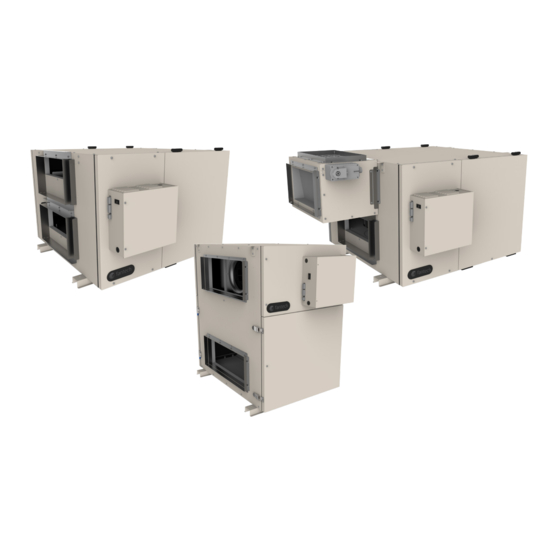
Commercial Heat Recovery Ventilators
SHR6904 • SHR6905R • SHR8004 • SHR11004 • SHR11005R • SHR14104
Your ventilation system should be installed in conformance with the appropriate provincial requirements or, in the absence of
such requirements, with the current edition of the National Building Code, and / or ASHRAE's "Good Engineering Practices".
United States
10048 Industrial Blvd., Lenexa, KS, 66215
Tel.: 800.747.1762 • Fax: 800.487.9915
Canada
50 Kanalflakt Way, Bouctouche, NB, E4S 3M5
Tel.: 800.565.3548 • Fax: 877.747.8116
Fantech reserves the right to modify, at any time and without notice, any or all of its products' features, designs,
components and specifications to maintain their technological leadership position.
Please visit our website www.fantech.net for more detailed technical information.
Installation Manual
Item #: 427685
Rev Date: 2018-02-02
Advertisement
Chapters
Table of Contents

Subscribe to Our Youtube Channel
Related Manuals for Fantech SHR6904


Summary of Contents for Fantech SHR6904
- Page 1 50 Kanalflakt Way, Bouctouche, NB, E4S 3M5 Tel.: 800.565.3548 • Fax: 877.747.8116 Fantech reserves the right to modify, at any time and without notice, any or all of its products’ features, designs, components and specifications to maintain their technological leadership position.
- Page 2 Note Warning/ Information Technical Practical tip Important information note PLEASE READ THIS MANUAL BEFORE INSTALLING UNIT Before installation, careful consideration must be given to how this system will operate if connected to any other piece of mechanical equipment, i.e. a forced air furnace or air handler, operating at a higher static pressure. After installation, the compatibility of the two pieces of equipment must be confirmed by measuring the airflows of the Heat / Energy Recovery Ventilator.
-
Page 3: Table Of Contents
SHR6904 ........ -
Page 4: Installation
Installation Location The HRV must be located in a heated space where it will be possible to conveniently service the unit. Typically the HRV would be located in the mechanical room, above a drop ceiling or an area close to the outside wall where the weatherhoods will be mounted. Attic installations are not normally recommended due to extreme temperatures, and difficulty in performing required service &... -
Page 5: Port Configuration
Port configuration The unit has access doors on the front and back. Also, the main control panel may be moved from front to back allowing for ducting layout. SHR 6904, SHR 6905R, SHR 11004, SHR 11005R WARM SIDE COLD SIDE WARM SIDE COLD SIDE Factory Setting. -
Page 6: Installing Duct Connections
Installing ducts going to / from outside Installing the ducting to the weatherhoods Outside weatherhoods The weatherhoods must have built-in "bird" screens with 1/4 inch (6.35 mm) minimum mesh to prevent birds and rodents from entering into the ductwork. Do not use smaller mesh as it will be very susceptible to plugging up. The preferred location of the weatherhoods is: •... -
Page 7: Airflow Balancing
A professional air balancer should be contacted to commission the system properly. A skilled HVAC Tech may complete the balance of air providing they possess the proper equipment. Call Fantech Technical support for assistance. -
Page 8: Installing The Bpm
Installing BYPASS Module (BPM) - SHR6905R/SHR11005R Kit content • 1x BPM assembly Bracket "A" • 1x bracket "A" • 2x bracket "B" Bracket "B" • 10x Screws • 1x black extension wire* • 1x red extentson wire* * Only used when electrical box is reversed Figure 1 Figure 2... -
Page 9: Installation Examples
Installation examples * Drawings are illustrations only and actual port locations and airflow directions may vary, consult unit spec sheets. It is the responsibility of the installer to ensure all ductwork is sized and installed as designed to ensure the system will perform as intended. The amount of air (CFM) that an HRV will deliver is directly related to the total external static pressure (E.S.P.) of the system. -
Page 10: Partially Dedicated Systems (Indirect Connections)
Installation examples (Cont'd) * Drawings are illustrations only and actual port locations and airflow directions may vary, consult unit spec sheets. It is the responsibility of the installer to ensure all ductwork is sized and installed as designed to ensure the system will perform as intended. The amount of air (CFM) that an HRV will deliver is directly related to the total external static pressure (E.S.P.) of the system. -
Page 11: Modes Of Operation
Modes of operation 1. Continuous / Ventilation Mode In this mode of operation both fans are operating and exchanging air with the outside. The heat recovery ventilator (HRV) constantly exchanges the air at the rate you select, either at low or medium speed, and switches to high speed when activated by an optional remote Stale Air from Inside control. -
Page 12: Speed Setting
Setting speed CAUTION MAKE SURE THE POWER TO THE UNIT IS DISCONNECTED BEFORE MAKING ANY CHANGES The HRV is shipped from the factory on low speed, intermittent operation can be obtained by toggling switch located on outside of cabinet. The voltage selection for low (reduced) speed of the unit is done via jumpers shown in the illustration below. The default setting 75V. Configurable speed control for low (reduced) speed Low: 75V Low: 90V... -
Page 13: Low Voltage Control Systems
Low Voltage Control Systems * Please see instruction manuals for individual controls for proper wiring and set up of control systems. CENTRAL CONTROLS These control options can only be used individually Ensure that unit is not CONTROLS FEATURES CONNECT TO plugged when connecting ECO-Touch®... -
Page 14: Maintenance
Maintenance CAUTION MAKE SURE UNIT IS UNPLUGGED BEFORE ATTEMPTING ANY MAINTENANCE WORK The following components should also be inspected regularly and well maintained. filters The motor - The motors are factory balanced and lubricat- The filters need to be checked and cleaned once a month or when they appear dirty. ed for life. - Page 15 Wiring Diagram SHR6904/SHR8004/SHR11004/SHR14104 HIGH...
-
Page 16: Shr6905R / Shr11005R
Wiring Diagram SHR6905R/SHR11005R HIGH... - Page 17 WIRING DIAGRAM (CONT'D) WIRING DIAGRAM TO Standard Furnace Interlock Wiring FURNACE THERMOSTAT TERMINALS FOUR WIRE TWO WIRE heating only FOR A FURNACE CONNECTION TO A COOLING SYSTEM: On some newer furnaces and older FURNACE thermostats, energizing the R and 24-VOLT TERMINAL BLOCK G terminal at the furnace has the COOLING SYSTEM...
-
Page 18: Shr 6904 / Shr8004 / Shr11004 / Shr14104
Installation Verification Test SHR 6904, SHR 8004, SHR 11004, SHR 14104 Models Without external control 1. Fan speed selector switch • Set fan Speed selector switch to Standby. 2. Start-up • Apply power to unit • Unit should enter Exhaust only defrost mode for a 10 second duration and the following should occur: Exhaust fan runs in HIGH (Normal) speed Supply fan remains off 3. -
Page 19: Shr6905R / Shr11005R
Installation Verification Test SHR 6905R, SHR 11005R Models Without External Control 1. Fan speed selector switch • Set fan Speed selector switch to Standby. 2. Start-up • Apply power to unit • Unit should enter Recirculation mode for a 10 second duration and the following should occur: Supply fan runs in HIGH (Normal) speed Exhaust fan remains off 3. - Page 20 • The heat recovery aluminum core has a lifetime warranty. • Fantech HRV's have a warranty that is limited to 3 years on all parts from the date of purchase, including parts replaced during this time period. If there is no proof of purchase available, the date associated with the serial number will be used for the beginning of the warranty period.
- Page 21 50 Kanalflakt Way, Bouctouche, NB, E4S 3M5 Tél.: 800.565.3548 • Fax: 877.747.8116 Fantech se réserve le droit de modifier partiellement ou entièrement, en tout moment et sans préavis, les caractéristiques, la conception, les composants et les spécifications de ses produits, afin de conserver sa position de leader de technologie.
- Page 22 Note Avertissement/ Information Information Conseil Note importante technique pratique PLEASE READ THIS MANUAL BEFORE INSTALLING UNIT Avant de procéder à l’installation, examinez avec soin la façon dont le système fonctionnera s’il est relié à tout autre appareil mécanique, notamment une fournaise à air pulsé ou un appareil de traitement d’air dont la pression statique est plus élevée.
- Page 23 SHR6904 / SHR8004 / SHR11004 / SHR14104........
-
Page 24: Installation
Installation EMPLACEMENT Le ventilateur-récupérateur de chaleur doit être situé dans un endroit chauffé où il est possible d'en faire l'entretien facilement. Généralement, le ventilateur-récupérateur de chaleur se situe dans la chambre des appareils mécaniques, au-dessus d'un plafond suspendu ou dans un endroit près du mur extérieur où... -
Page 25: Configuration Des Ports
Configuration des ports L'appareil possède des portes d'accès à l'avant et l'arrière. De plus, on peut déplacer le panneau de commande principal de l'avant vers l'arrière, afin de faciliter la configuration du système de gaines. SHR 6904, SHR 6905R, SHR 11004, SHR 11005R Côté... -
Page 26: Installation Des Conduits
Installation des conduits extérieurs Installer le système de conduit aux hottes Hottes extérieurs Les capots doivent posséder des grillages aviaires intégrés d'au moins 1/4 po (6,35 mm) pour éviter que les oiseaux et les rongeurs n'entrent dans le système de gaines. Ne pas utiliser de grillage plus petit, car il sera plus susceptible de se bloquer. L'emplacement de choix pour les capots est : •... -
Page 27: Équilibrage Du Débit D'air
Dans les immeubles qui ne possèdent pas de systèmes CVAC à air forcé, l'air frais doit être fourni dans toutes les zones habitables. Celui-ci doit être fourni à partir d'endroits à mur ou plafonds élevés. On recommande des grilles qui diffusent de l'air confortable, par exemple la grille Fantech {MGE (métal) ou CG (plastique) avec un effet Coanda. -
Page 28: Installation Du Bpm
Installation du module de déviation (BPM) - SHR6905R/SHR11005R Contenu du Kit • 1x Assemblé BPM Support "A" • 1x support "A" • 2x support "B" Support "B" • 10x Vis • 1x extension de fil noir* • 1x extension de fil rouge* * Utilisé... -
Page 29: Exemples D'installation
Exemples d'installation * Les dessins ne sont que des illustrations et les emplacements des entrées réelles et les directions des débits d'air peuvent varier. Consulter les fiches signalétiques des appareils. L'installateur doit s'assurer d'installer et de dimensionner tous les systèmes de gaines comme indiqué, afin que le système fonctionne comme prévu. La quantité... -
Page 30: Système Partiellement Dédidé (Connexion Indirecte)
Exemples d'installation (Suite) * Les dessins ne sont que des illustrations et les emplacements des entrées réelles et les directions des débits d'air peuvent varier. Consulter les fiches signalétiques des appareils. L'installateur doit s'assurer d'installer et de dimensionner tous les systèmes de gaines comme indiqué, afin que le système fonctionne comme prévu. -
Page 31: Modes De Fonctionnement
Modes d'opération 1. Mode continu / de ventilation Dans ce mode de fonctionnement, les deux ventilateur fonctionnent et échangent l'air avec l'extérieur. Le ventilateur récupérateur de chaleur (VRC) échange continuellement l'air à la vitesse que vous choisissez, Air vicié de soit à... -
Page 32: Configurer La Vitesse
Configurer la vitesse AVERTISSEMENT ASSUREZ-VOUS QUE L'ALIMENTATION DE L'UNITÉ EST DÉCONNECTÉE AVANT DE FAIRE DES CHANGEMENTS Le VRC est expédié de l'usine à basse vitesse, un fonctionnement intermittent peut être obtenu par un commutateur de basculement situé à l'extérieur de l'armoire. La sélection de la tension pour la basse vitesse (réduite) de l'unité... -
Page 33: Systèmes De Contrôle À Basse Tension
SYSTÈME DE CONTRÔLE À BASSE TENSION * Veuillez voir les instructions individuelles des contrôles pour le câblage et la mise en pièce appropriée. CONTRÔLES CENTRALS Ces options de contrôle peuvent seulement être utilisé individuellement Assurez-vous que CONTRÔLE CARACTÉRISTIQUES CONNEXION À l'appareil n'est pas ECO-Touch®... -
Page 34: Entretien
Entretien AVERTISSEMENT S'ASSURER QUE L'APPAREIL EST DÉBRANCHÉ AVANT D'Y RÉALISER TOUT TRAVAIL D'ENTRETIEN On doit aussi inspecter les composants suivants régulièrement et les entretenir adéquatement. Filtres Moteur - Les moteurs sont équilibrés en usine et On doit vérifier et nettoyer les filtres une fois par mois ou lorsqu'ils semblent sales. lubrifiés à... -
Page 35: Connexions Électriques
Connexions électriques SHR6904/SHR8004/SHR11004/SHR14104 HIGH... -
Page 36: Shr6905R / Shr11005R
Connexions électriques SHR6905R/SHR11005R HIGH... - Page 37 SCHÉMAS ÉLECTRONIQUES (SUITE) CONNEXION ÉLECTRIQUE Câblage standard de synchronisation avec une fournaise Standard Furnace Interlock Wiring À UNE FOURNAISE BORNES DU THERMOSTAT TERMINALS TERMINALS FOUR QUATRE FILS WIRE DEUX FILS TWO WIRE chauffage seulement heating only DANS LE CAS D'UNE FOURNAISE RACCORDÉE À...
-
Page 38: Test De Vérification De L'installation
Test de vérification de l'installation Modèls SHR 6904, SHR 8004, SHR 11004, SHR 14104 Sans contrôle externe 1. Commutateur de sélection de vitesse du ventilateur • Réglez le sélecteur de vitesse du ventilateur en mode Attente (Standby) 2. Mise en service •... - Page 39 Test de vérification de l'installation Modèles SHR 6905R, SHR 11005R Sans contrôle externe 1. Commutateur de sélection de vitesse du ventilateur • Réglez le sélecteur de vitesse du ventilateur en mode Attente (Standby) 2. Mise en service • Placez l'appareil en marche •...
- Page 40 • L'élément central de l'appareil est garanti à vie. • Les ventilateurs-récupérateurs de chaleur Fantech détiennent une garantie de trois (3) ans sur toutes les pièces à partir de la date d'achat, y compris les pièces remplacées pendant cette période. Si aucune preuve d'achat n'est disponible, on utilisera la date associée au numéro de série comme date d'entrée en vigueur de la garantie.
-
Page 41: Shr6904
Parts list • Liste des composantes SHR6904 BOM # Description SHR6904 (40417) Motor Assy, R2E 250-BC51 403475 Electrostatic Filters Kit 11.5” x 15” 40482 Heat Recovery Cell 12” x 12” x 15” 402064 x2 Kit Drain Plug 40315 x2 Drain, T... -
Page 42: Shr6905R
Parts list • Liste des composantes SHR6905R BOM # Description SHR6905R (41047) Motor Assy, R2E 250-BC51 403475 Electrostatic Filters Kit 11.5” x 15” 40482 Heat Recovery Cell 12” x 12” x 15” 402064 x2 Kit Drain Plug 40315 x2 Drain, T 410788 PCB, RV-CTRL 422677... -
Page 43: Shr8004
Parts list • Liste des composantes SHR8004 BOM # Description SHR8004 (40443-1) Motor Assy, R2E 250-AW-57 411728 Electrostatic Filters Kit 11.5” x 15” 40482 Heat Recovery Cell 12” x 12” x 15” 402064 x2 Kit Drain Plug 40315 x2 Drain, T 410788 PCB, RV-CTRL 422677... -
Page 44: Shr11004
Parts list • Liste des composantes SHR11004 BOM # Description SHR11004 (40419) Motor Assy, R2E 250-BC51 403475 Electrostatic Filters Kit 11.5” x 15” 40459 Heat Recovery Cell 12” x 12” x 15” 402064 x3 Kit Drain Plug 40315 x2 Drain, T 410788 PCB, RV-CTRL 422677... -
Page 45: Shr11005R
Parts list • Liste des composantes SHR11005R BOM # Description SHR11005R (41048) Motor Assy, R2E 250-BC51 403475 Electrostatic Filters Kit 11.5” x 15” 40459 Heat Recovery Cell 12” x 12” x 15” 402064 x3 Kit Drain Plug 40315 x2 Drain, T 410788 PCB, RV-CTRL 422677... -
Page 46: Shr14104R
Parts list • Liste des composantes SHR14104 BOM # Description SHR14104 (40438-1) Motor Assy, R2E 250-AW-57 411728 Electrostatic Filters Kit 11.5” x 15” 40459 Heat Recovery Cell 12” x 12” x 15” 402064 x3 Kit Drain Plug 40315 x2 Drain, T 410788 PCB, RV-CTRL 422677... - Page 47 Notes...
- Page 48 Fantech reserves the right to make technical changes. Fantech se réserve le droit de faire des changements For updated documentation please refer to www.fantech.net techniques. Pour de la documentation à jour, s'il vous plaît se référer au www.fantech.net Fantech® Fantech®...
Need help?
Do you have a question about the SHR6904 and is the answer not in the manual?
Questions and answers